
bending machine

A technology of a bending machine and a bending mechanism, which is applied in the field of bending machines, can solve the problems of low manual operation efficiency, low worker safety and high labor cost, and achieves the advantages of improving operation safety, reducing labor cost and improving work efficiency. Effect

Inactive Publication Date: 2015-11-11
NINGBO ZHENHAI SHILI ELECTROMECHANICAL
View PDF10 Cites 3 Cited by
  • Summary
  • Abstract
  • Description
  • Claims
  • Application Information

AI Technical Summary

Problems solved by technology

[0002] In the production of various candlesticks and shelves, the poles are generally bent and then welded and fixed to form products, while traditional bending machines are generally operated manually, which is inefficient, high labor costs, and low worker safety.

Method used


Image

  • bending machine
  • bending machine
  • bending machine

Examples


Embodiment Construction

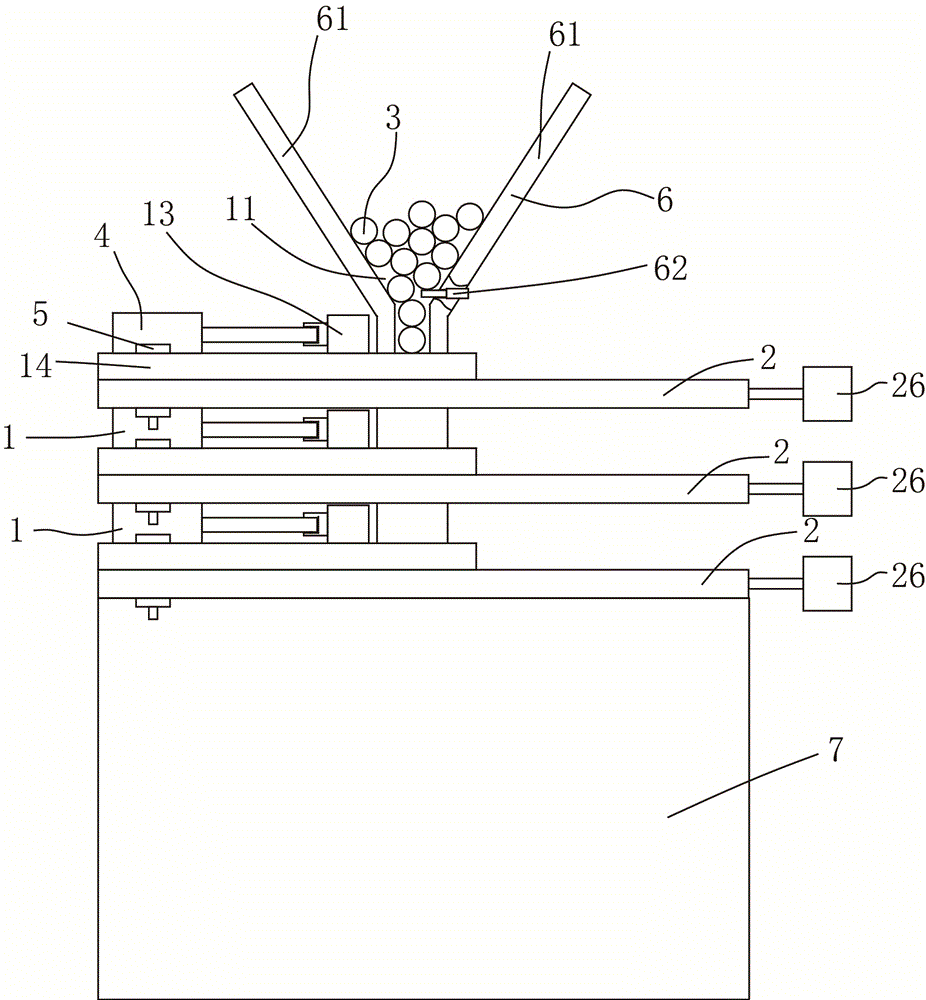
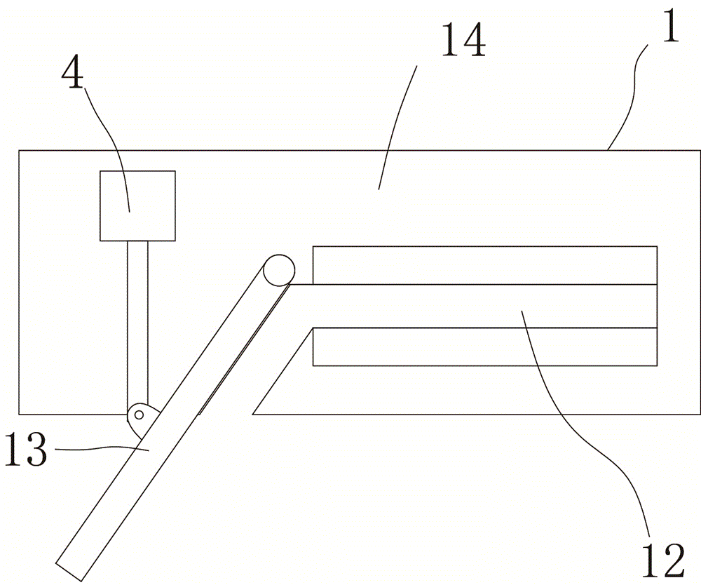
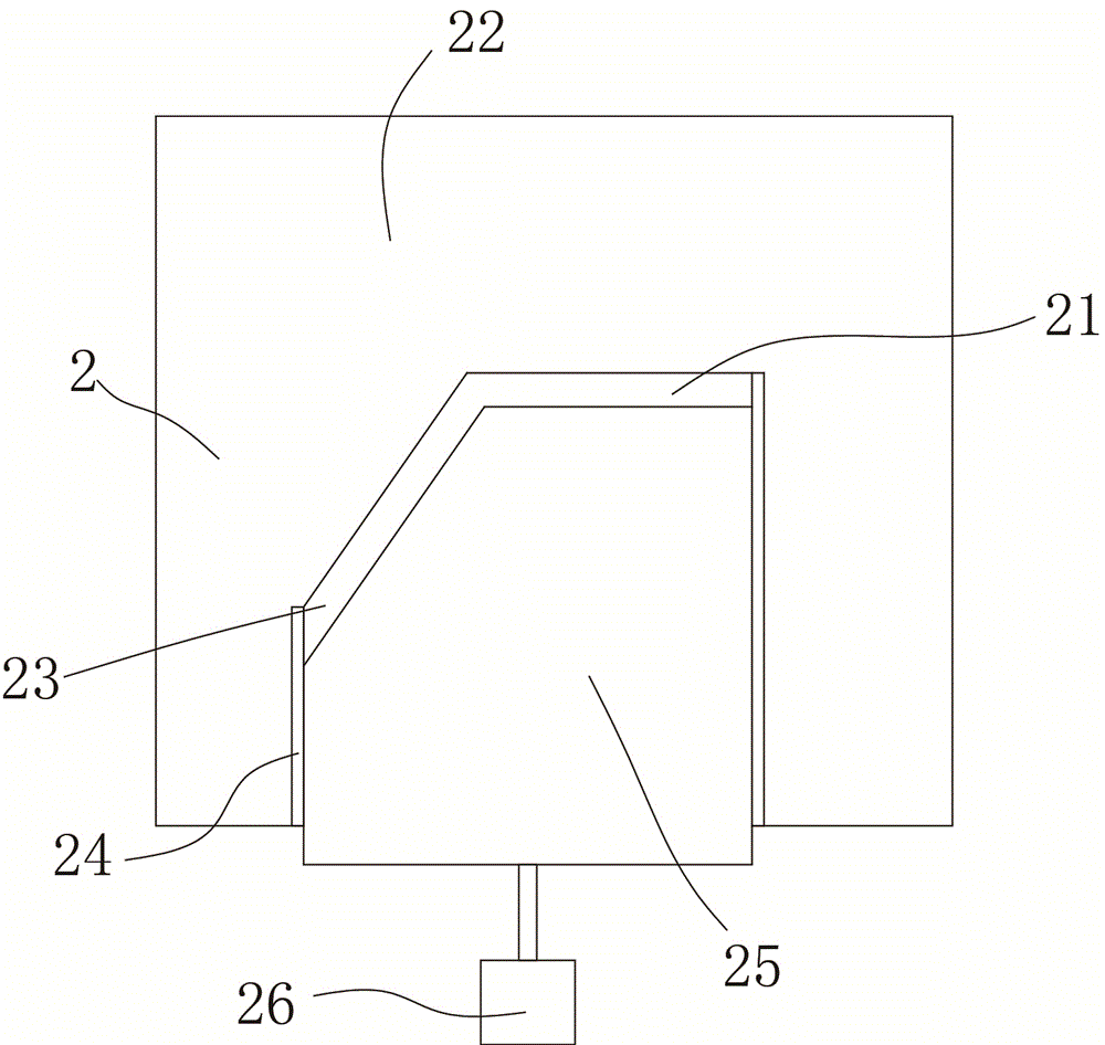
[0012] The present invention will be described in further detail below in conjunction with accompanying drawing and specific embodiment: see Figure 1 to Figure 3 , a bending machine, including several bending mechanisms 1 stacked together, a feeding port 11 is arranged above the bending mechanism 1 at the uppermost end, and a partition 2 is arranged between each of the bending mechanisms 1 , the Different blanking through-holes 21 are provided on the partition 2, and the shape of the blanking through-holes 21 matches with the shape of the rod body 3 (processed material) bent by the bending mechanism 1 above. The bending mechanism 1 includes Fixing groove 12, rotating rod 13 and base plate 14, described rotating rod 13 is connected with described base plate 14 rotation, is connected with driving device 4 on the described rotating rod 13, and described driving device 4 is all connected with control device (not shown on the figure) Out), in this embodiment, the driving device 4 ...


PUM


Abstract

The invention discloses a bending machine. The bending machine comprises a plurality of bending mechanisms which are stacked together. A feed port is formed above the uppermost bending mechanism, a partition plate is arranged between every two bending mechanisms, a discharging through hole is formed in each partition plate, and each discharging through hole is matched with a rod formed by bending the bending mechanism above the discharging through hole in shape. Each bending mechanism comprises a fixing groove, a rotating rod and a bottom plate, the rotating rod is rotationally connected with the bottom plate, a driving device is connected to each rotating rod, and all the driving devices are connected with a control device. A storage hopper is connected above the feed port, and an anti-blocking air cylinder is arranged at the lower end of the storage hopper. Through the bending machine, automatic bending can be achieved, working efficiency can be improved, labor cost can be reduced, operating safety is improved, and the feed port of the bending machine can be prevented from getting stuck.

Description

technical field [0001] The invention relates to a bending machine, which is mainly used for bending metal rods, and is used for producing metal candle holders, metal wall hangings and the like. Background technique [0002] In the production of various candlesticks and shelves, the poles are generally bent and then welded and fixed to form products. However, traditional bending machines are generally operated manually. Manual operation is inefficient, labor costs are high, and workers’ safety is low. It is easy to get caught. Contents of the invention [0003] The invention provides a bending machine aimed at the deficiencies of the prior art, which can realize automatic bending, improve work efficiency, reduce labor costs, improve operation safety, and prevent the bending machine from being stuck at the feeding port. [0004] In order to solve the above-mentioned technical problems, the present invention solves the problem through the following technical solutions: the be...

Claims


Application Information

Patent Timeline
Patent Type & Authority Patents(China)
IPC IPC(8): B21D7/024
Inventor 邱益锋
Owner NINGBO ZHENHAI SHILI ELECTROMECHANICAL
Learn More