
Gear milling cutter unit

A technology for milling cutters and gears, which is applied to gear tooth manufacturing devices, gear tooth manufacturing tools, belts/chains/gears, etc. It can solve the problems of lower workpiece quality, poor surface finish, and increased tool costs, and achieve machining dimensional accuracy High, good surface finish, and the effect of reducing equipment cost

Active Publication Date: 2017-03-01
NINGBO CHUANJINGYU MECHANICAL TECH DEV
View PDF6 Cites 0 Cited by
  • Summary
  • Abstract
  • Description
  • Claims
  • Application Information

AI Technical Summary

Problems solved by technology

The gear shaping processing efficiency is low; the cutting tool material is high-speed steel, which wears out quickly during the processing process, which not only increases the cost of the cutting tool, but also makes it difficult to ensure stable dimensional accuracy, resulting in poor consistency of the processed products
The dimensional accuracy of gear hobbing is not high, and the surface finish is not high, thus reducing the quality of the workpiece
Moreover, the above two processing methods require special gear shaping machines and gear hobbing machines, which makes the cost of processing equipment higher
At present, in the field of mechanical processing, the application of milling cutters to the processing of gears and racks has not yet appeared, and the present invention appears to meet this need

Method used


Image

  • Gear milling cutter unit
  • Gear milling cutter unit
  • Gear milling cutter unit

Examples


Embodiment Construction

[0025] The present invention will be further described below in conjunction with the drawings and specific embodiments.

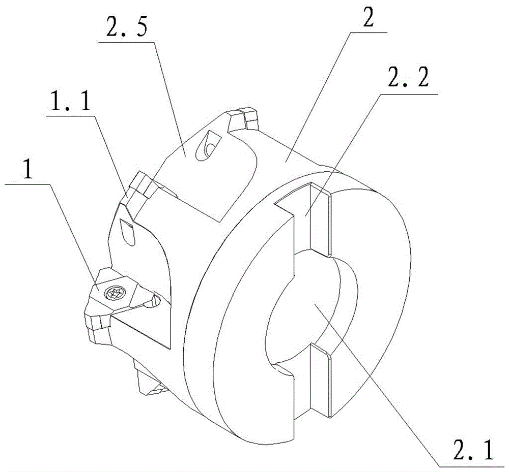
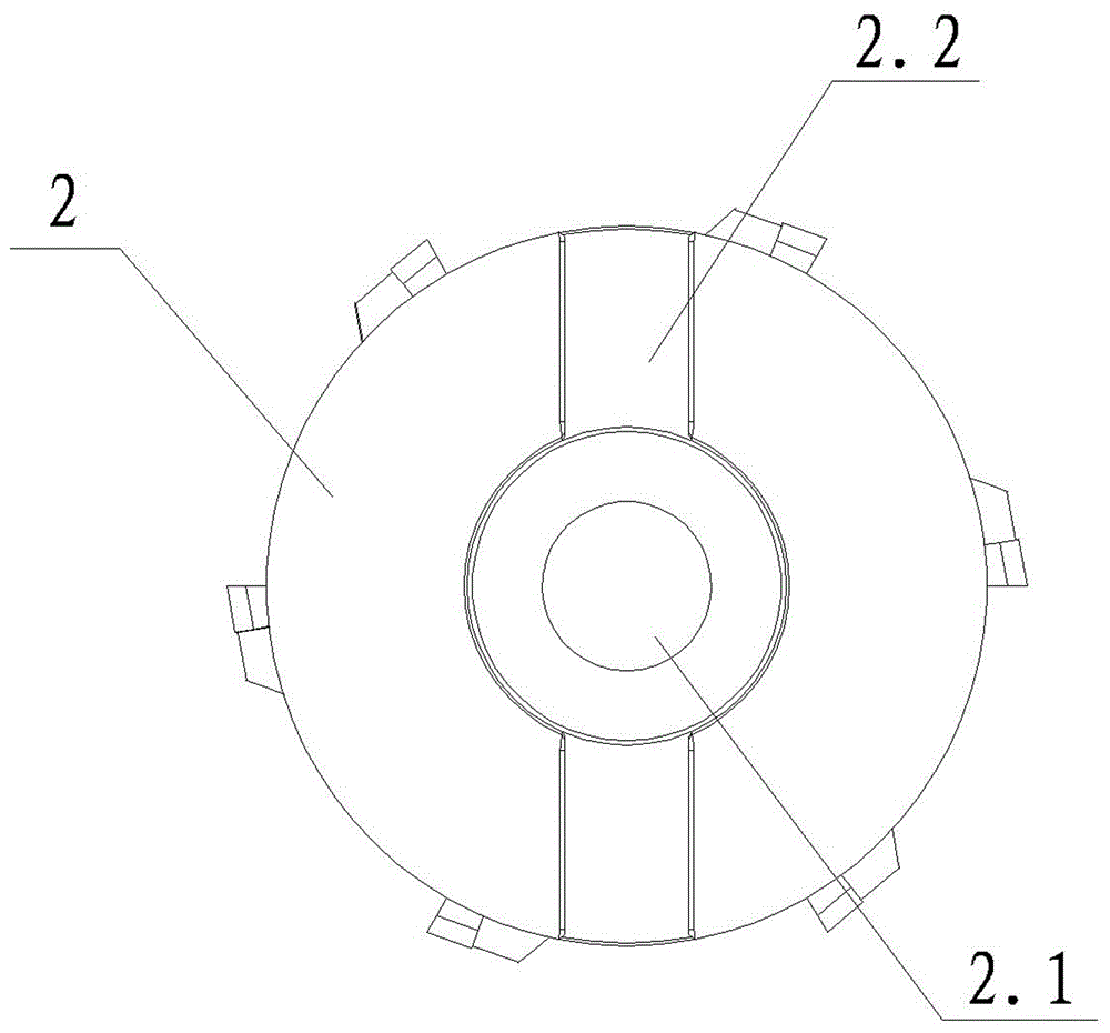
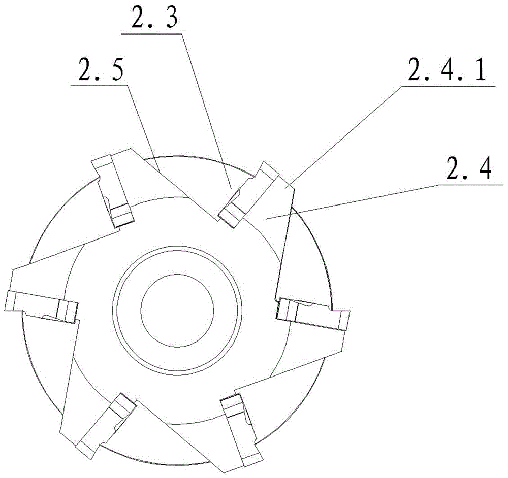
[0026] See figure 1 , figure 2 , image 3 and Figure 4 As shown, the gear milling cutter device of the present invention includes a blade 1 and a cutter head 2. The center of the cutter head 2 is provided with a drive shaft hole 2.1. A limit slot 2.2 is provided on the end surface of one end of the cutter head 2, and the limit slot 2.2 is in communication with the drive shaft hole 2.1. At least one knife slot 2.3 is cut radially inwardly on the circumferential surface of the cutter head 2. A blade seat 2.4 is provided on the side wall of the knife slot 2.3. The blade 1 is installed on the blade seat 2.4 and the cutter head 1.1 of the blade 1 is exposed outside the circumferential surface of the cutter head 2. The outer side wall of the blade seat 2.4 protrudes radially along the cutter head 2 to form an extension 2.4.1 for supporting the blade 1 cutter he...


PUM


Abstract

The invention discloses a gear milling cutter device which comprises blades (1) and a cutter head (2). A drive shaft hole (2.1) is formed at the center of the cutter head. At least one cutter holding groove (2.3) is axially inwardly cut in the circumferential surface of the cutter head (2). Blade seat (2.4) are disposed on the side wall of each cutter holding groove (2.3). The blades (1) are mounted on the blade seat (2.4). The tool bit (1.1) of each blade (1) is exposed out of the circumferential surface of the cutter head (2). The shape of the cross section of each tool bit (1.1) is matched with that of the cross section of the toothed groove of a to-be-machined gear. The gear milling cutter device is high in machining efficiency, low in cutter cost, high in machining size precision and high in surface smoothness, and equipment cost can be lowered.

Description

Technical field [0001] The invention relates to the technical field of machining cutting tools, and more specifically to a gear milling cutter device for milling gears and racks. Background technique [0002] A milling cutter is a rotary cutter with one or more teeth used for milling. When working, each cutter tooth intermittently cuts off the margin of the workpiece. The milling cutter device has the advantages of high processing efficiency, precise processing size, and low processing cost. The milling cutter device includes a blade and a cutter head. The blade has a sharp edge and cuts briskly. The milling cutter device is a standard machine tool, which can process metal parts with medium to high hardness and strength, and can also be used for processing non-metallic materials. When milling a workpiece in machining, the cutter head of the milling cutter is usually inserted on the spindle of the machine tool, and the spindle of the machine tool drives the milling cutter to ro...

Claims


Application Information

Patent Timeline
Patent Type & Authority Patents(China)
IPC IPC(8): B23F21/12
Inventor 袁国智任元平
Owner NINGBO CHUANJINGYU MECHANICAL TECH DEV
Learn More