
vehicle anti-collision device

An anti-collision device and vehicle technology, applied in the direction of the bumper, can solve the problems of limited anti-collision cushioning effect, inconvenient use, and the inability of the bumper 91 to pivot and move, so as to achieve the effect of improving the safety protection function

Inactive Publication Date: 2016-04-13
詹宏洋
View PDF6 Cites 0 Cited by
  • Summary
  • Abstract
  • Description
  • Claims
  • Application Information

AI Technical Summary

Problems solved by technology

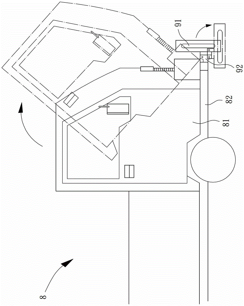
[0004] However, the existing vehicle anti-collision device 9 is only connected to the crossbeam 82 of the flat-headed vehicle 8 with the two fixing plates 92, so that the vehicle anti-collision device 9 is only suitable for bearing the force of frontal impact on the lower half; that is Said, when the impact force is oblique or acts on the bumper 91 by the upper part, the impact force cannot be effectively transmitted to the beam 82 with the highest structural strength of the flat-headed vehicle 8, so that the vehicle anti-collision device 9 The anti-collision cushioning effect that can be provided is quite limited, not only the bumper 91 is very easy to be deformed and damaged, but also more likely to cause injury to the personnel riding in the flat-top car 8, so its safety protection function is not good
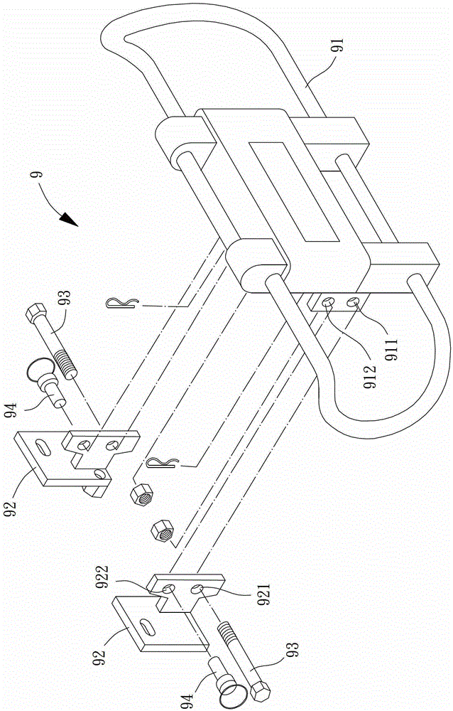
[0005] In addition, due to the pivot joint of the bumper 91 and the fixed plate 92 (combination structure of the pivot screw 93, the shaft hole 911 and the pivot hole 921) and the positioning position (the position of the fixed pin 94, the fixed pin hole 912 and the through hole 922 combination structure) are not provided with anti-collision cushioning structure; therefore, when the vehicle anti-collision device 9 is subjected to a strong impact force, the pivot joints and positioning positions of the bumper 91 and the fixing plate 92 are quite easy to be damaged, and then produce such as The bumper 91 cannot pivot and the fixed pin 94 cannot be disassembled, etc.
Furthermore, when the bumper 91 is intended to pivot forward, the fixing pin 94 must be removed first, which causes inconvenience in use.

Method used


Image

  • vehicle anti-collision device
  • vehicle anti-collision device
  • vehicle anti-collision device

Examples


Embodiment Construction

[0076] In order to make the above-mentioned and other objects, features and advantages of the present invention more comprehensible, the preferred embodiments of the present invention are specifically cited below, together with the accompanying drawings, as follows:

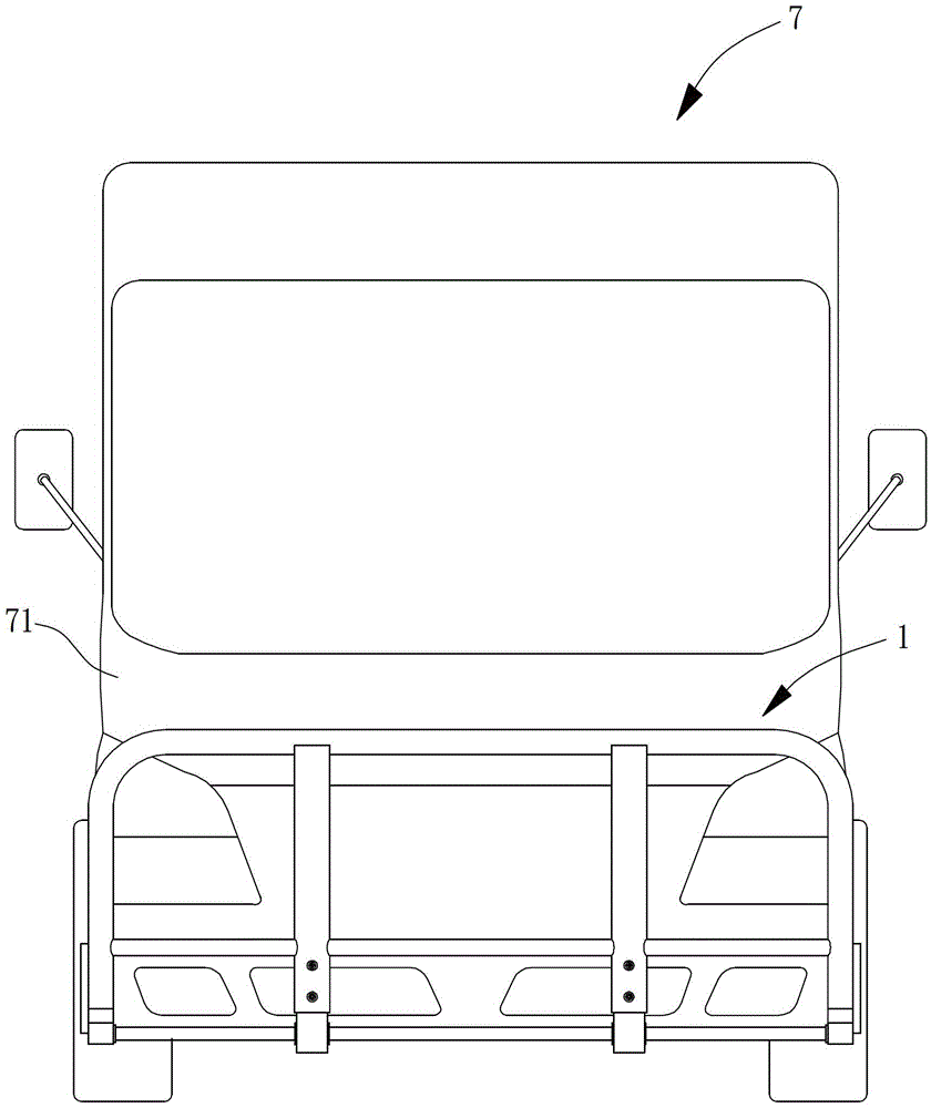
[0077] Please refer to image 3 , 4 As shown, the vehicle anti-collision device of the preferred embodiment of the present invention is installed on the front end of the front 71 of a car body 7, and the bottom of the car body 7 has two girders 72, which are the structures in the car body 7. The position with the highest strength, and a part of the two girders 72 extend at the bottom of the front 71; the bottom of the car body 7 is additionally provided with two shock absorbers 73, and the two shock absorbers 73 are respectively formed by two fixing parts 731 is connected to the corresponding girder 72 . In addition, the vehicle body 7 is further provided with a headstock rotating shaft 74, which connects the h...


PUM


Abstract

A vehicle collision prevention device is used to solve the problems that prior bumper bars are only suitable for bearing front collision force and need manual pivot control. The vehicle collision prevention device comprises two solid joint modules which are respectively connected with two cross beams of a vehicle body, a bumper bar which is pivoted onto the two solid joint modules and provided with at least one support pillar connected with a corresponding amount of bumper blocks so as to abut a vehicle head rotation shaft, and a fastening module which is provided with a clamp hooking component and a positioning component which are mutually clamped, wherein the clamp hooking component is arranged on the bumper bar, and the positioning component is combined with the front end of a vehicle head.

Description

technical field [0001] The invention relates to a vehicle component, in particular to a vehicle anti-collision device installed at the front end of the vehicle to buffer the impact force. Background technique [0002] Please refer to figure 1 , 2 , which is the vehicle anti-collision device 9 disclosed in the patent case of China Taiwan Announcement No. 297348 "The Bumper Structure of the Liftable Front". This existing vehicle anti-collision device 9 includes a bumper 91 and two left and right symmetrical A fixed plate 92. The bumper 91 is provided with several shaft holes 911 and several fixing pin holes 912; the two fixing plates 92 are arranged in front of the front 81 of the flat-head truck 8, and are connected to the crossbeam 82 of the flat-head truck 8, and the two fixed Corresponding to the shaft hole 911 and the fixing pin hole 912 of the bumper 91 , the plate 92 is also provided with a plurality of pivot holes 921 and a plurality of through holes 922 . The shaf...

Claims


Application Information

Patent Timeline
Patent Type & Authority Patents(China)
IPC IPC(8): B60R19/02B60R19/26
Inventor 詹宏洋
Owner 詹宏洋
Learn More