A steering wheel provided with an airbag module positioning device
A technology of positioning device and airbag, which is applied to steering control, pedestrian/occupant safety arrangement, vehicle safety arrangement and other directions installed on the vehicle, can solve problems such as inconvenience for drivers to use, avoid abnormal steering wheel noise and reduce noise , the effect of eliminating the free movement gap
- Summary
- Abstract
- Description
- Claims
- Application Information
AI Technical Summary
Problems solved by technology
Method used
Image
Examples
Embodiment 1
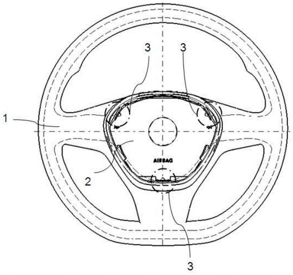
[0040] see image 3 with Figure 4 , in this example, the steering wheel body 1 is composed of a metal frame wrapped with foam material, the airbag module 2 includes a door cover 21, an inflator 22, a housing 23 and a horn system 24, and the space between the steering wheel body 1 and the airbag module 2 is Positioning devices 3 are provided on the contact surface of the airbag module 2. The outer surface of the door cover 21 of the airbag module 2 is provided with a guide boss 211. The positioning devices 3 are distributed symmetrically with respect to the central axis. There are three positioning devices 3 in this example.
[0041] see Figure 5 , the positioning device 3 includes a mounting bracket 11 and an elastic element 12 , the mounting bracket 11 is arranged on the inner wall of the housing of the steering wheel body 1 , and the elastic element 12 is fixed on the mounting bracket 11 .
[0042] The mounting bracket 11 includes an outer frame 111 , fastening buckles 1...
Embodiment 2
[0049] The following combination Figure 12 The second embodiment of the present invention will be described, and the same components as those in the first embodiment will not be described again.
[0050] see Figure 12 , in this example, the elastic element 12 includes a support frame 121 , an elastic arm 122 , an elastic clip 123 and an arc-shaped convex surface 124 . Wherein, the elastic arm 122 is provided with a straight half-waist hole 5, which extends straight to the upper edge of the support frame 121, and one end on both sides of the elastic arm 122 is connected with the upper edge of the support frame 121. The other end of the two sides of 122 extends to the upper end of the arc-shaped convex surface 124, that is, the two sides of the elastic arm 122 jointly form an elastic structure of a cantilever beam, and the two sides of the elastic arm 122 are arranged in parallel. The two sides of the elastic arm 122 can effectively improve and adjust the elastic force of th...
Embodiment 3
[0053] The following combination Figure 13 The third embodiment of the present invention will be described, and the same components as those of the previous embodiment will not be described again.
[0054] see Figure 13 , in this example, the elastic element 12 includes a support frame 121 , an elastic arm 122 , an elastic clip 123 and an arc-shaped convex surface 124 . Wherein, the elastic arm 122 is composed of two elastic ribs 122a, the elastic ribs 122a are L-shaped, the longitudinal ends of the two elastic ribs 122a are respectively connected with the upper edge of the support frame 121, and the transverse ends of the two elastic ribs 122a extend to the arc respectively. The two sides of shaped convex surface 124. There is a certain distance between the two elastic ribs 122a of the elastic arm 122, so that the elastic arm 122 is more easily deformed, and the L-shaped elastic rib 122a structure effectively increases the distance between the two elastic ribs 122a, there...
PUM
 Abstract
Description
Claims
Application Information
 - R&D
- Intellectual Property
- Life Sciences
- Materials
- Tech Scout
- Unparalleled Data Quality
- Higher Quality Content
- 60% Fewer Hallucinations
Browse by: Latest US Patents, China's latest patents, Technical Efficacy Thesaurus, Application Domain, Technology Topic, Popular Technical Reports.
© 2025 PatSnap. All rights reserved.Legal|Privacy policy|Modern Slavery Act Transparency Statement|Sitemap|About US| Contact US: help@patsnap.com


