Fertilization position and transport position changeover mechanism for paddy field fertilization device

A technology of a fertilization device and a conversion mechanism, which is applied in the directions of fertilization devices, fertilizer distributors, applications, etc., can solve the problems of inability to achieve independent adjustment, poor adaptability, and independent control, and achieve simple and convenient conversion and adjustment, improve adaptability, and use reliable results

Inactive Publication Date: 2014-07-23
NORTHEAST AGRICULTURAL UNIVERSITY
View PDF5 Cites 1 Cited by
  • Summary
  • Abstract
  • Description
  • Claims
  • Application Information

AI Technical Summary

Problems solved by technology

[0002] At present, the paddy field fertilization operation is completed by fixing the paddy field fertilization device on various paddy field operation tools to form a composite operation tool, such as rice transplanting and fertilizing machine, paddy field weeding and fertilizing machine, paddy field rotary tillage and land preparation operation machinery, etc. The conversion of the two states of transportation and transportation needs to be realized by changing the height and position of various compound machines and tools, which cannot be controlled separately, especially when fertilization operations can be completed and realized independently according to job requirements. Adjustment of a single fertilization device, adaptability Difference

Method used


Image

  • Fertilization position and transport position changeover mechanism for paddy field fertilization device
  • Fertilization position and transport position changeover mechanism for paddy field fertilization device
  • Fertilization position and transport position changeover mechanism for paddy field fertilization device

Examples


Embodiment Construction

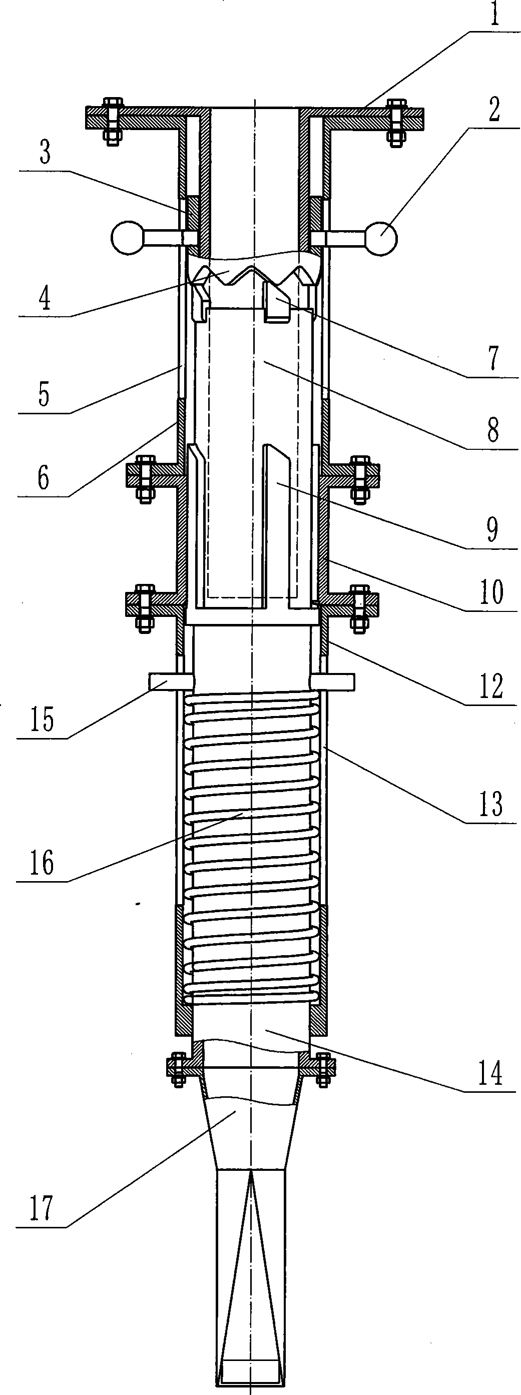
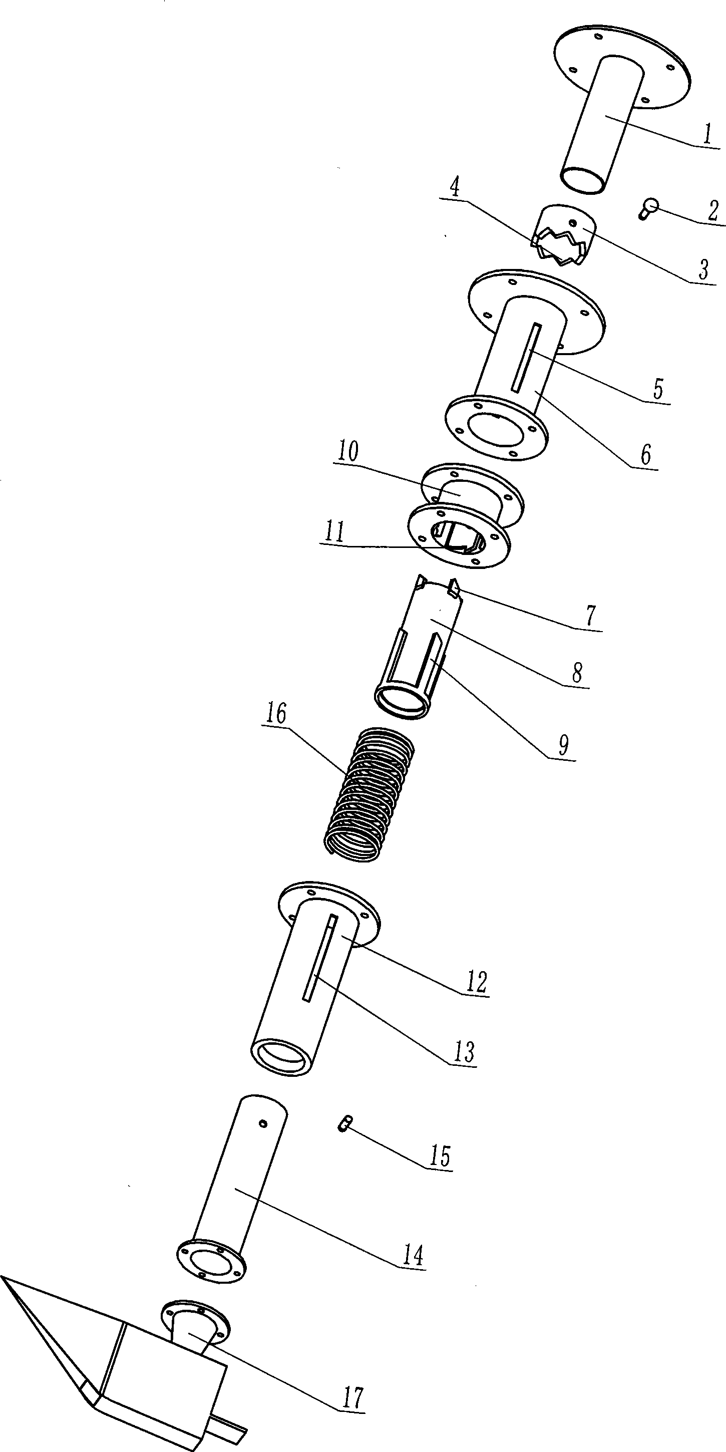
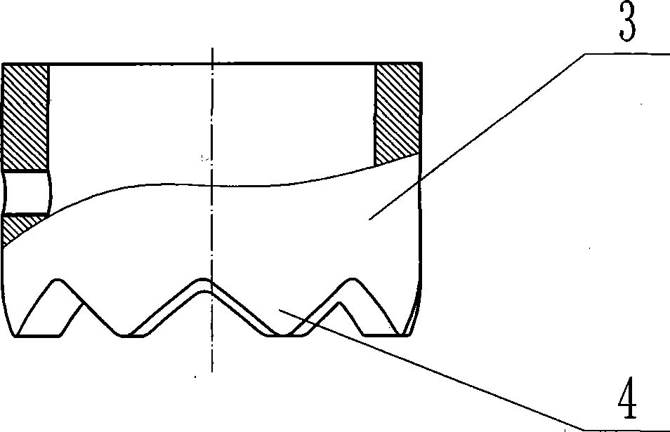
[0013] Embodiments of the present invention will be described in detail below in conjunction with the accompanying drawings. A fertilization position and transport position conversion mechanism for a paddy field fertilization device, the upper sleeve 6 and the lower sleeve 12 are respectively fixed on the upper and lower parts of the guide sleeve 10, and the inner wall surface of the guide sleeve 10 is set in the axial direction. The bit boss 11, on the wall of the upper sleeve 6, an upper chute 5 is axially symmetrically provided, and on the wall of the lower sleeve 12, a sliding groove 13 is provided axially symmetrically, and the expansion and contraction of the sleeve pressure spring 16 The tube 14 is mated and installed in the lower sleeve 12, and the positioning pin 15 is axially movable and inserted in the sliding groove 13. The inner end of the positioning pin 15 is connected with the telescopic tube 14, and the upper end of the pressure spring 16 Contact and cooperate...


PUM


Abstract

The invention discloses a fertilization position and transport position changeover mechanism for a paddy field fertilization device and belongs to agricultural machinery. An upper sleeve and a lower sleeve are respectively fixedly arranged on the upper part and the lower part of a guide sleeve; a telescopic pipe sleeved by a pressure spring is inserted into the lower sleeve; a positioning pin is inserted into a lower chute in the lower sleeve; the inner end of the positioning pin is connected with the telescopic pipe; a fertilization boot is assembled on the lower end part of the telescopic pipe; a rotary round tube with short and long boss teeth is inserted into the guide sleeve; a boss-type sleeve is inserted into the upper sleeve; an adjusting hand lever is inserted into an upper chute in the upper sleeve; the inner end of the adjusting hand lever is connected with the boss-type sleeve; a sleeve liner is fixedly arranged on the upper part of the upper sleeve. According to the mechanism, changeover and adjustment of the fertilization position and transport position of a single fertilization device is realized, the adaptive capacity of paddy field operating machines and tools assembled with the fertilization device on different fertilization operating requirements is improved, and the mechanism has the characteristics of novel and reasonable structural design, simplicity and convenience in adjustment and operation and reliability in application.

Description

technical field [0001] The invention belongs to agricultural machinery, and mainly relates to a position conversion mechanism of a fertilizing device equipped on a rice transplanting and fertilizing machine, a paddy field weeding and fertilizing machine, and a paddy field rotary tillage and soil preparation machine. Background technique [0002] At present, the paddy field fertilization operation is completed by fixing the paddy field fertilization device on various paddy field operation tools to form a composite operation tool, such as rice transplanting and fertilizing machine, paddy field weeding and fertilizing machine, paddy field rotary tillage and land preparation operation machinery, etc. The conversion of the two states of transportation and transportation needs to be realized by changing the height and position of various compound machines and tools, which cannot be controlled separately, especially when fertilization operations can be completed and realized indepen...

Claims


Application Information

Patent Timeline
Patent Type & Authority Applications(China)
IPC IPC(8): A01C15/00
Inventor 王金峰杨欣伦王金武周韦
Owner NORTHEAST AGRICULTURAL UNIVERSITY
Why Eureka
Try Eureka