
Turning device and turning mechanism using the turning device

A flipping device and flipping axis technology, which is applied in applications, home appliances, and removable tables, etc., can solve the problems of identification barriers, inability to realize the control of desktop flipping, and insufficient convenience, and achieve the effect of expanding the field of use

Active Publication Date: 2016-04-27
HANGZHOU DECHANG HARDWARE FURNITURE
View PDF5 Cites 0 Cited by
  • Summary
  • Abstract
  • Description
  • Claims
  • Application Information

AI Technical Summary

Problems solved by technology

[0002] At present, in order to adapt to the needs of folding and placing or adjusting the angle of the desktop, all kinds of tables usually need to turn the desktop over. This type of table is usually called a flip table or a folding table. When turning over, it is usually necessary to understand the movement mode of the pull rod or wrench. At the same time, good cooperation between the two hands is required, so that there are certain identification obstacles and inconvenient when turning over, and the existing technology generally cannot realize the control of part of the desktop turning over.

Method used


Image

  • Turning device and turning mechanism using the turning device
  • Turning device and turning mechanism using the turning device
  • Turning device and turning mechanism using the turning device

Examples


Embodiment Construction

[0022] The implementation of the present invention has multiple flexible modes, detailed description is as follows:

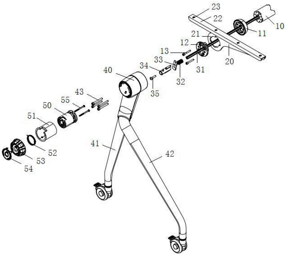
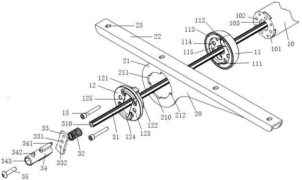
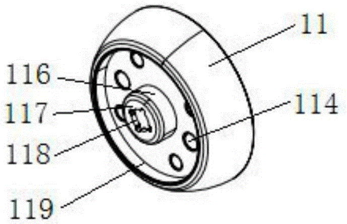
[0023] Such as Figure 1 to Figure 6 As shown, the circular connecting piece 101 is welded at the end of the round tubular beam 10, and there is a circular through hole 103 at the center of the connecting piece 101, and it is assembled with the turning shaft assembly one 11, the turning piece 20, and the turning shaft assembly two 12 in order And the screw 13 is screwed together through the through hole on the turning shaft assembly one 11 and the turning shaft assembly two 12 and the screw hole 102 on the connecting piece 101. The turning shaft assembly one 11 is cylindrical, and has a cylindrical The groove is set on the end of the beam 10, and has a smooth end surface 113 in the direction of the turning shaft assembly 2 12, and also has a cylindrical groove. The turning shaft assembly 2 12 is composed of two sections of cylinders, and the intersection of the...


PUM


Abstract

The invention discloses a turnover device. The turnover device comprises a turnover part and a turnover shaft. The turnover part is provided with a turnover shaft sleeve in a slab type. A round through hole is formed in the middle of the turnover shaft sleeve. The turnover shaft sleeve is installed on the turnover shaft in a sleeved mode and rotates relative to the turnover shaft. A locating groove is formed in the round through hole. A locating piece is arranged and matched with the locating groove. The locating piece and the locating groove are in embedded fit so as to fix the turnover part relative to the turnover shaft. One side of the locating piece is connected with one end of a pull rod. The other end of the pull rod is provided with a screwing assembly in screwing fit with a screwing assembly on a rotor. The rotor is cylindrical. A fixed shell is arranged outside the rotor. The rotor rotates in the fixed shell. A rotation reset device is arranged between the rotor and the fixed shell, so that the relative positions of the rotor and the fixed shell are kept. The invention further discloses a turnover mechanism using the turnover device. By the turnover device and the turnover mechanism using the turnover device, turning over is controlled in a rotating mode, control over turning can be achieved in an anticlockwise rotating mode or clockwise rotating mode, and consequently great convenience is brought to turnover operation.

Description

technical field [0001] The present invention relates to a turning table device, more specifically, relates to a turning device, which is mainly used for controlling the turning of the desktop in a simple way when the turning of the desktop is required. Background technique [0002] At present, in order to meet the needs of folding and placing or adjusting the angle of the desktop, all kinds of tables usually need to turn the desktop over. This type of table is usually called a flip table or a folding table. When turning over, it is usually necessary to first understand the movement mode of the pull rod or wrench. At the same time, good cooperation between the two hands is required, so that there are certain identification obstacles and inconvenient convenience when turning over, and the prior art generally cannot realize the control of partial desktop turning. For this reason, the present invention provides a kind of brand-new overturning device. Contents of the invention ...

Claims


Application Information

Patent Timeline
Patent Type & Authority Patents(China)
IPC IPC(8): A47B17/00A47B3/00A47B41/02
Inventor 陈德昌
Owner HANGZHOU DECHANG HARDWARE FURNITURE
Learn More