Electric heating pressure stewing utensil

A cooking utensil and pressure technology, which is applied in the direction of pressure cooker, steam cooking utensils, cooking utensils, etc., can solve the problems of increasing production costs, and achieve the effects of saving energy, improving food cooking quality, and reducing ambient temperature

Inactive Publication Date: 2014-07-23
王永光
View PDF7 Cites 3 Cited by
  • Summary
  • Abstract
  • Description
  • Claims
  • Application Information

AI Technical Summary

Problems solved by technology

However, this method not only increases the production cost, but also produces side effects when used in summer when the ambient temperature is high.

Method used


Image

  • Electric heating pressure stewing utensil
  • Electric heating pressure stewing utensil
  • Electric heating pressure stewing utensil

Examples


Embodiment 1

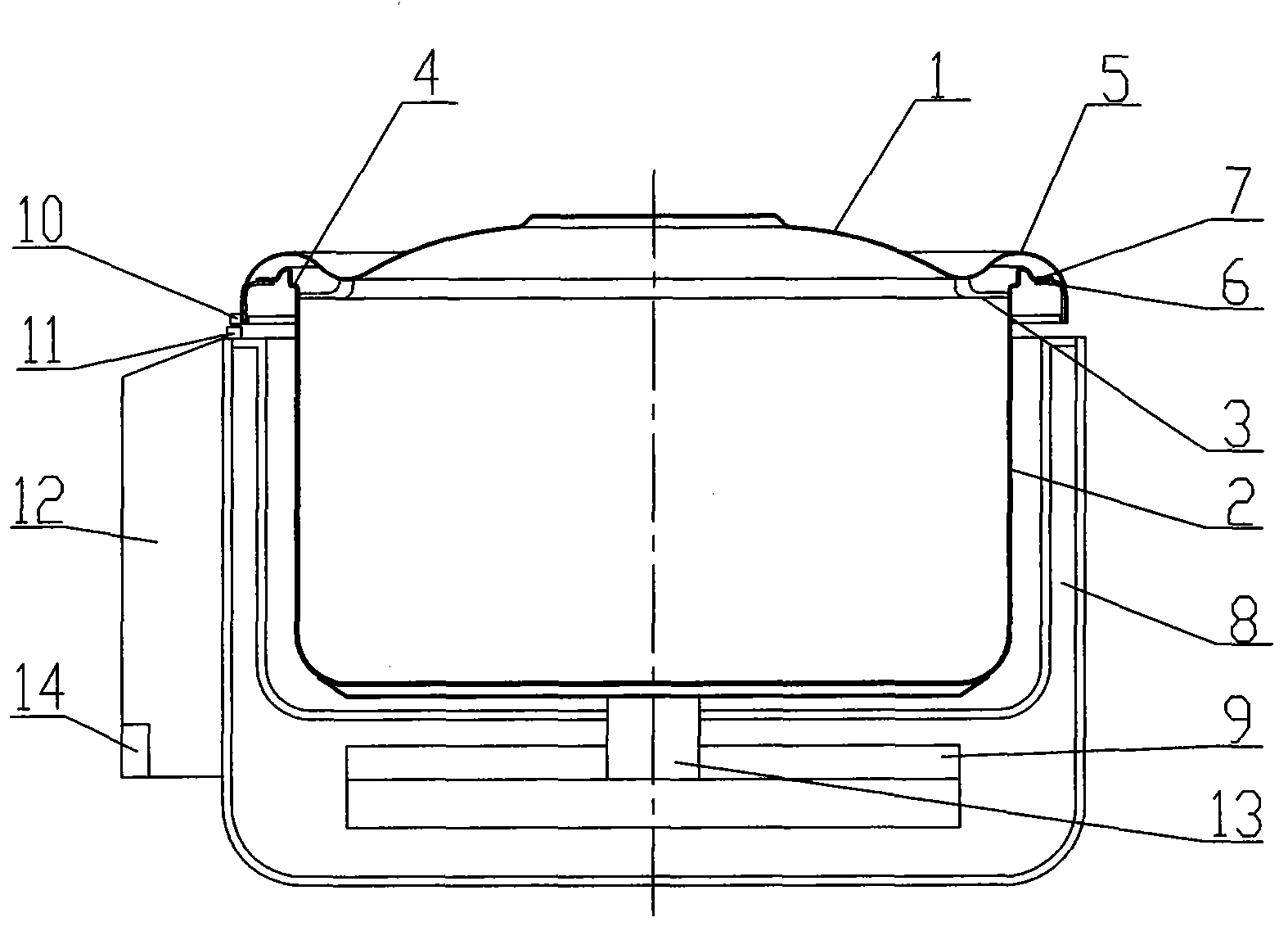
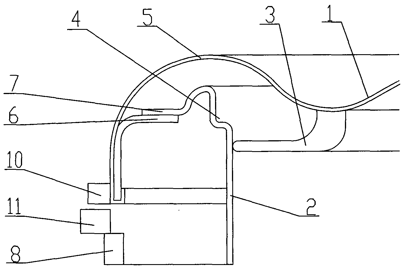
[0025] Embodiment 1: see figure 1 , figure 2 , Figure 5 , Figure 6 . The pot cover 1, the pot body 2 and the elastic structural member 5 are all made of stainless steel plates. The connection structure of this embodiment adopts a right-handed screw structure: the elastic structural member 5 is made into a corrugated shape, and one end thereof is fixedly arranged on the outer edge of the pot cover 1 or integrated with the pot cover 1 . At the other end of the elastic structural member 5, 6 cap teeth 6 with a small rise angle (such as 2°) are evenly arranged along the circumference. Combined with the elastic displacement parameters of the elastic structural member 5, the vertical elevation difference between the head end and the end of the cap tooth 6 is selected within the range of several millimeters. Six pot teeth 7 matched with the lid teeth 6 are set along the circumference on the upper mouth of the pot body 2 .

[0026] The sealing ring 3 is made of silicon rubber...

Embodiment 2

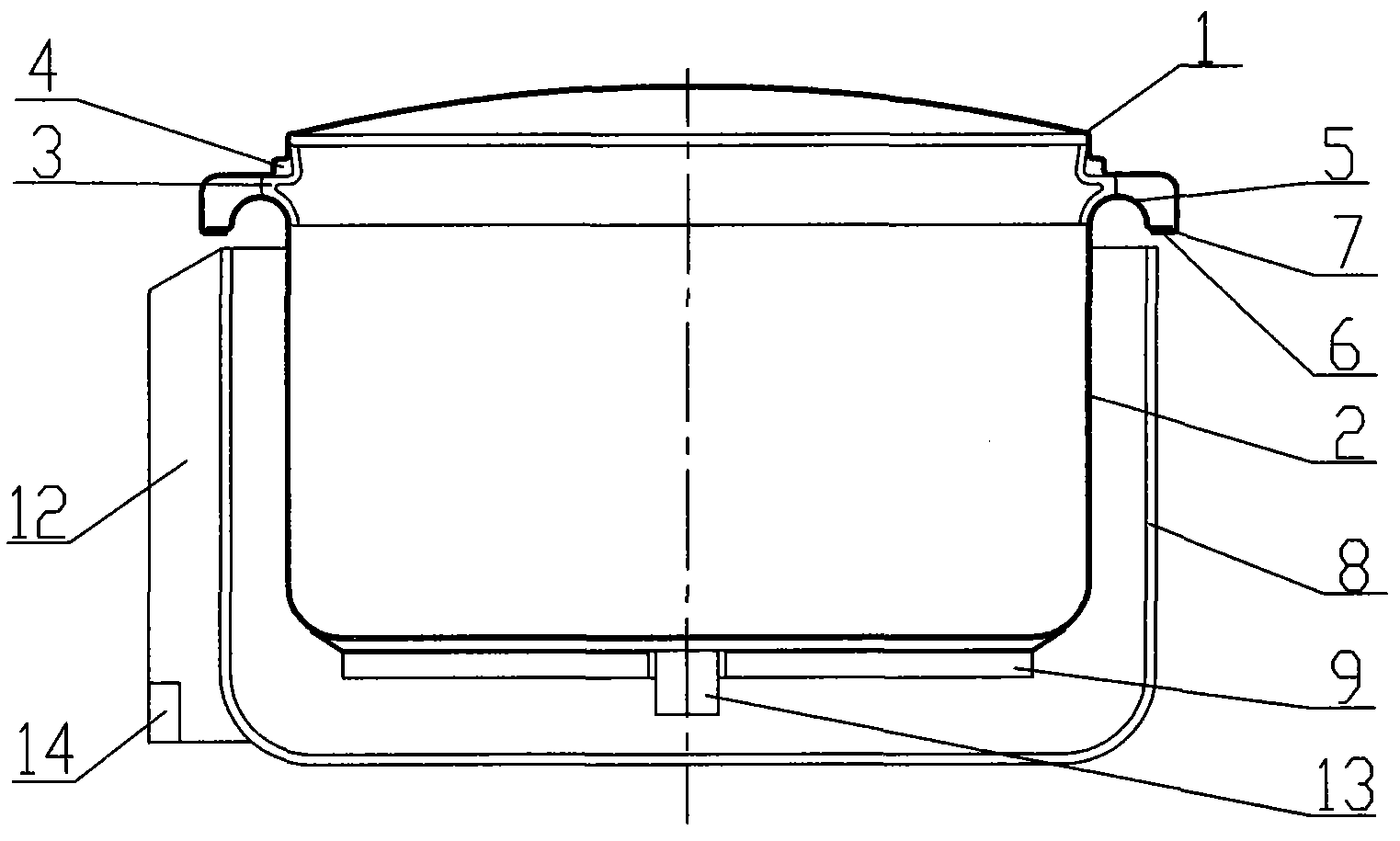
[0031] Example 2: see image 3 , Figure 4 . The pot cover 1, the pot body 2 and the elastic structural member 5 are all made of high-quality stainless steel plates. The connecting structure of this embodiment adopts the right-handed flat tooth structure. The elastic structural member 5 is arranged on the mouth of the pot body 2: one end of the elastic structural member 5 is fixed on the mouth of the pot body 2 or is integrated with the pot body 2, and the other end is provided with six pot teeth 7 along the circumference. The outer edge of the pot cover 1 is provided with 6 cover teeth 6 matched with the above-mentioned pot teeth 7 .

[0032] The sealing ring 3 is made of silicon rubber, and one end of the sealing ring 3 is fixed on the mouth of the pot body 2 by a fixed structure, so that the other end and the pot cover 1 form a dynamic seal. Six pressure relief grooves 4 are arranged on the sealing part of the pot cover 1 along the circumference. The pressure relief gr...


PUM


Abstract

The invention provides an electric heating pressure stewing utensil and belongs to a pressure type electric heating stewing utensils for kitchens. The electric heating pressure stewing utensil comprises a pot cover, a pot body, a sealing ring, a pressure relief groove and an elastic structural member. One end of the elastic structural member is arranged on the pot cover or the pot body. The other end of the elastic structural member is provided with a connecting structure matched with the pot body or the pot cover. The sealing ring is arranged between the pot cover and the pot body. The pressure relief groove is formed at the sealed portion of the pot body or the pot cover. The electric heating pressure stewing utensil further comprises a control system and an electric heater arranged at the bottom of the pot body. The control system is connected with the electric heater, an electric heating time control device, a cooking temperature control device and the like. Due to the arrangement of the threaded connecting structure and a position sensing device and technologies like program control, the problem that people need to watch a utensil to control and adjust the heating degree and time in cooking in the prior art is solved, selection on pressure and time is programmed and standardized when food is cooked, and the electric heating pressure stewing utensil has the advantages of being high in safety, high in degree of automatic control, easy and convenient to operate and low in production cost.

Description

Technical field: [0001] The invention belongs to pressure-type electric heating cooking utensils for kitchens. Background technique: [0002] Although the existing common pressure cooker has the advantages of saving time and energy, the steam exhaust channel in its exhaust steam limiting device and overpressure relief device all adopts a slender tubular structure. The viscous liquid, particles and chips etc. of the food in the cooking are easy to block the above-mentioned slender tube type exhaust steam passage, causing frequent explosion accidents that seriously endanger the personal and property safety of consumers. In addition, because the screw-in pressure cooker is not in place during use, the connection strength between the pot cover and the pot body is not enough, which is also a reason for the explosion accident. Chinese patents ZL01110532.1 and ZL2004100572609 disclose a technical solution of a safety pressure cooker, which form an unblockable The unique dynamic s...

Claims


Application Information

Patent Timeline
Patent Type & Authority Applications(China)
IPC IPC(8): A47J27/08A47J27/04A47J36/00
Inventor 王永光
Owner 王永光
Why Eureka
Try Eureka