Auxiliary power supply system for motor train unit and fault load reducing method

A technology of power supply system and EMU, which is applied in electric vehicles, current collectors, electrical devices, etc., can solve the high reliability requirements of four-quadrant converters and auxiliary power supply systems, and the high redundancy requirements of auxiliary power supply systems , the auxiliary power supply system has no power and other problems, so as to ensure the comfort of passengers, the optimization of power supply, and the stability and reliability of power supply.

Active Publication Date: 2014-07-23
CRRC QINGDAO SIFANG ROLLING STOCK RES INST
View PDF6 Cites 32 Cited by
  • Summary
  • Abstract
  • Description
  • Claims
  • Application Information

AI Technical Summary

Problems solved by technology

[0005] The power supply mode of the auxiliary system of the Japanese EMU is to extract an auxiliary winding from the main traction transformer to change the network voltage to AC 400V, and after being rectified to intermediate DC by a pulse rectifier, it is then inverted into a controllable 400VAC / 50Hz three-phase AC power supply to On the auxiliary power supply bus, the advantage of this power supply mode is that the circuit structure is simple and the reliability is high. The disadvantage is that when passing through the phase separation area, the entire auxiliary power supply system is in a powerless state; the power supply mode of the auxiliary system of the European EMU is The auxiliary power supply windings of the traction transformers of each traction unit supply power. After passing through the four-quadrant converter to output the intermediate DC, it is converted into a controllable three-phase AC and supplied to the auxiliary power bus. When passing through the phase-splitting area, the entire auxiliary power supply system can be The uninterrupted power supply of the auxiliary system is realized by means of regenerative braking. The advantage of this power supply mode is that it can realize the uninterrupted power supply of the entire auxiliary power supply system. The disadvantage is that the reliability of the four-quadrant converter and auxiliary power supply system equipment is relatively high.
[0006] Now with the rapid development of railway technology, the free marshalling of trains will become the future development trend. The original auxiliary power supply system cannot flexibly change its power supply mode due to the free marshalling of trains. For the redundancy of the entire auxiliary power supply system , if one of the auxiliary power supply systems fails, the redundancy requirements for the adjacent auxiliary power supply systems are relatively high, and the resulting economic costs are relatively high

Method used


Image

  • Auxiliary power supply system for motor train unit and fault load reducing method
  • Auxiliary power supply system for motor train unit and fault load reducing method
  • Auxiliary power supply system for motor train unit and fault load reducing method

Examples


Embodiment 1

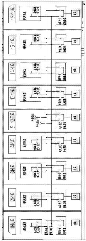
[0021] Such as figure 1 As shown, the present embodiment is a 16-group EMU, wherein the Mc car is the end car, the M car is the motor car, and the T car is the trailer, and the EMU compartments are numbered as 1-16 cars by the network positioning system.

[0022] As shown in Table 1, the medium-voltage load of the auxiliary power supply system of the 16-marshalled EMU is alternately connected to the I bus or the II bus according to the odd and even numbers of the EMU cars.

[0023] Table 1 Medium-voltage power supply mode and load distribution of auxiliary power supply system for 16-marshalled EMUs

[0024]

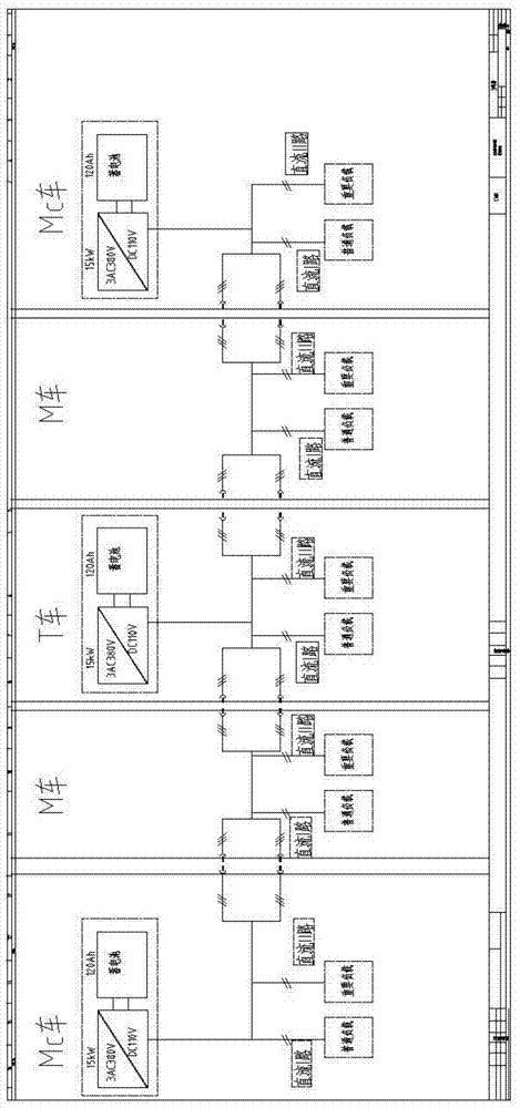
[0025] Such as image 3 As shown, the 15KW charger is figure 1 It is a kind of medium voltage load of medium EMU.

[0026] Auxiliary power supply system for 16-marshalling EMUs, including auxiliary converters, busbar I, busbar II, busbar connectors, contactor boxes, AC loads, and low-voltage power supply system. On the side, busbar I and busbar II run through the e...

Embodiment 2

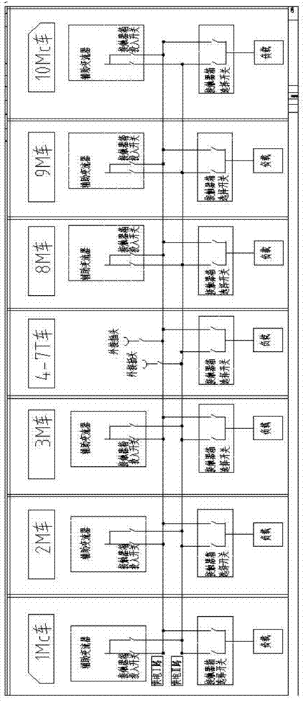
[0036] Such as figure 2 As shown, the present embodiment is a 10-group EMU, wherein the Mc car is the terminal car, the M car is the motor car, and the T car is the trailer, and the EMU compartments are numbered 1-10 cars by the network positioning system.

[0037] As shown in Table 2, the medium-voltage load of the auxiliary power supply system of the 10-marshalled EMU is alternately connected to the I bus or the II bus according to the odd and even numbers of the EMU cars.

[0038] Table 2 Medium-voltage power supply mode and load distribution of auxiliary power supply system for 10-marshalled EMUs

[0039]

[0040] Auxiliary power supply system for 10-marshalling EMUs, including auxiliary converters, busbar I, busbar II, busbar connectors, contactor boxes, AC loads, and low-voltage power supply system. On the side, busbar I and busbar II run through the entire column through the busbar connectors on both sides of the carriage, the auxiliary converters of 1Mc cars, 3M c...


PUM


Abstract

The invention relates to an auxiliary power supply system for a motor train unit and a power supply method and a load reducing method of the auxiliary power supply system. The auxiliary power supply system for the motor train unit comprises auxiliary current transformers, a bus I, a bus II, bus connectors, a contactor box, medium-voltage loads and a low-voltage power supply system. The bus I and the bus II penetrate through the whole auxiliary motor train unit through the bus connectors on the two sides of carriages. The auxiliary current transformers and the medium-voltage loads are connected with the bus I or the bus II alternately according to the parity number of the motor train unit carriages. Part of the medium-voltage loads of the motor train unit operate in a load reducing mode or are directly disconnected when the auxiliary current transformers break down. The auxiliary power supply system operates in a parallel connection mode through the buses penetrating through the whole auxiliary motor train unit, the relative concentration and flexible arrangement eliminating mode of the motor train unit is achieved, the requirement for the redundancy of each set of auxiliary current exchanging system is low, the economic cost is greatly reduced, the power supply of the whole train unit is stable and reliable, and the passenger comfort level and the running safety coefficient of the motor train unit are guaranteed.

Description

technical field [0001] The invention relates to an auxiliary power supply system for a high-speed train set, in particular to an auxiliary power supply system for a high-speed train set, its power supply mode and a load reduction method. Background technique [0002] Auxiliary power supply system is one of the important components of railway vehicles, which plays the role of supplying power to the medium and low voltage loads of the whole train, including lighting, air conditioning, heating, TV, etc. [0003] The auxiliary power supply system is mainly composed of auxiliary converters, chargers and batteries. The auxiliary converter plays the role of converting high-voltage direct current into three-phase AC380V / 50Hz to supply power for medium-voltage loads; the charger is an important part of converting three-phase AC380V / 50Hz into DC110V to supply power for low-voltage loads; the battery is used in emergencies It plays the role of power supply for low-voltage loads such a...

Claims


Application Information

Patent Timeline
Patent Type & Authority Applications(China)
IPC IPC(8): B60L1/00B60L3/00
Inventor 李博谢峥崔晓光张波位俊雷周扬杨东军李照平
Owner CRRC QINGDAO SIFANG ROLLING STOCK RES INST
Why Eureka
Try Eureka