Circuit board signal testing clamp

A signal test and circuit board technology, applied in the direction of electronic circuit test, measuring device casing, etc., can solve the problems of complex structure and inconvenient operation of the test clip, and achieve the effect of avoiding poor contact, simple structure and improving operation efficiency

Active Publication Date: 2014-07-23
STATE GRID CORP OF CHINA +3
View PDF9 Cites 5 Cited by
  • Summary
  • Abstract
  • Description
  • Claims
  • Application Information

AI Technical Summary

Problems solved by technology

[0009] The purpose of the present invention is to provide a circuit board signal test clip to solve the problems of complex structure and inconvenient operation of the existing test clip

Method used


Image

  • Circuit board signal testing clamp
  • Circuit board signal testing clamp

Examples


Embodiment Construction

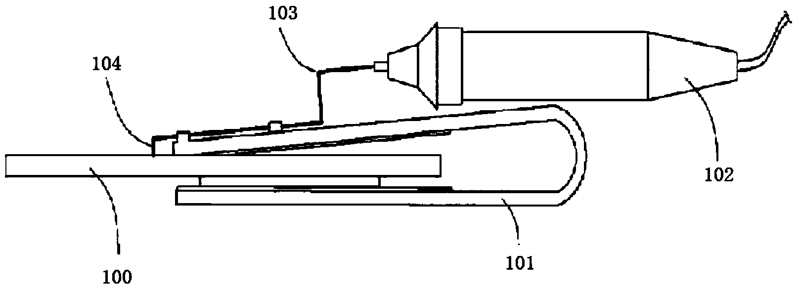
[0026] The basic solution of the present invention is: a circuit board signal test clip, including an upper clamping plate and a lower clamping plate for clamping the circuit board to be tested, the upper clamping plate is a PCB circuit board, and the PCB circuit board There are connecting wires on the board, one end of the connecting wire is used for connecting the test circuit, and the other end is used for connecting the probe.

[0027] The present invention will be described in further detail below in conjunction with the accompanying drawings.

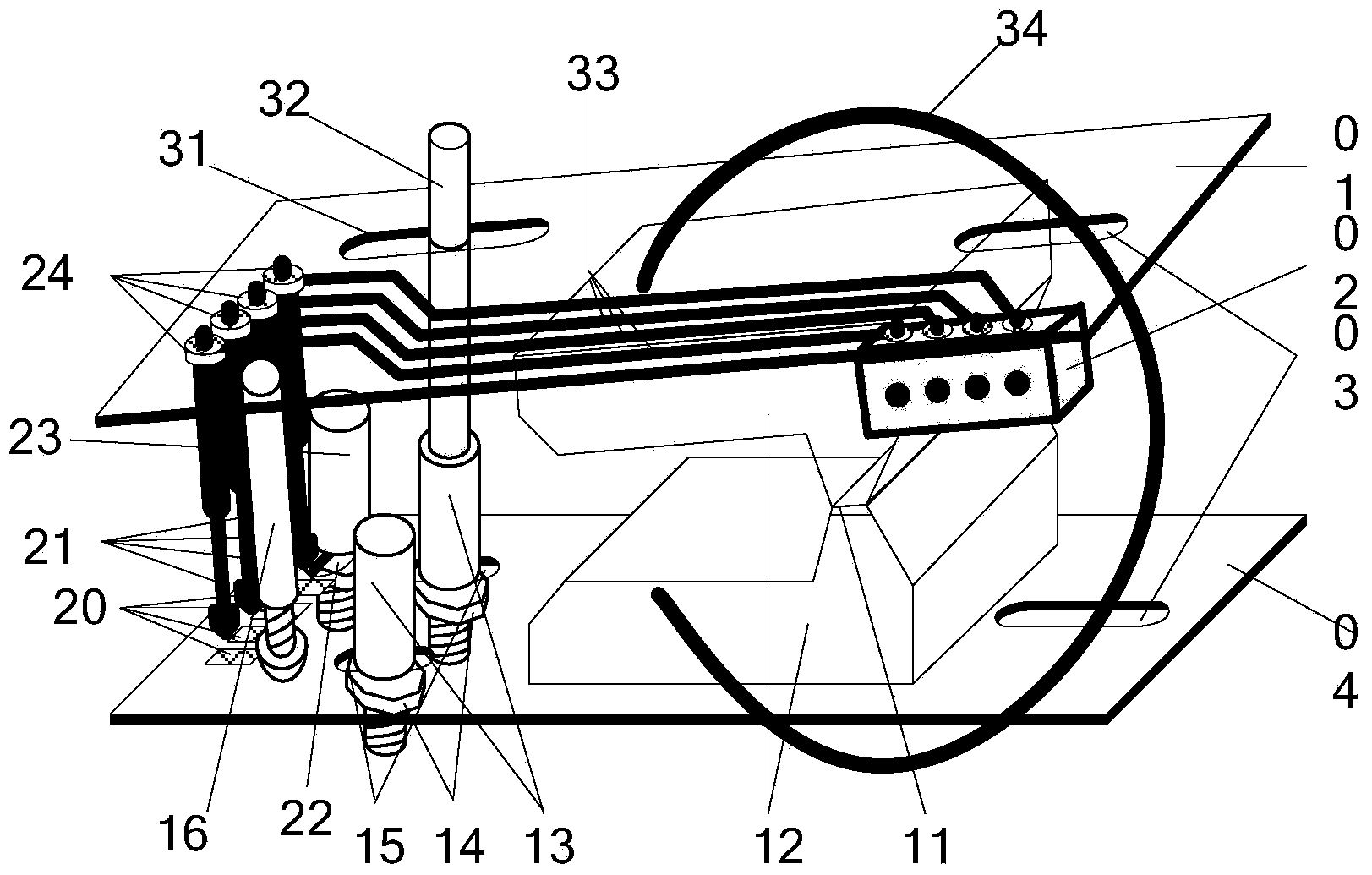
[0028] Such as figure 2 As shown, the upper clamping plate 01 and the lower clamping plate 02 are installed on two clamping parts of a spring clip 12 respectively, and 11 is the spring clip rotating shaft. The upper clamping board is a PCB circuit board, the connecting wire is fixed on the circuit board through the PCB process, one end of the connecting wire is connected to the interface device 02 through the corresponding pad, ...


PUM


Abstract

The invention relates to a circuit board signal testing clamp which comprises an upper clamping board and a lower clamping board which are used for clamping a circuit board to be tested. The circuit board signal testing clamp is characterized in that the upper clamping board is a PCB (01), the PCB (01) is provided with connecting wires (33), one ends of the connecting wires (33) are used for being connected with the circuit board to be tested, and the other ends of the connecting wires (33) are used for being connected with probes (21). According to the circuit board signal testing clamp, the connecting wires are fixed to the upper clamping PCB through the PCB technology, and contacts can be prevented from being deviated by the fact that the probes are pulled by the connecting wires; the PCB further brings convenience to fixing the probes through bonding pads and fixing a connector device (02), probe rods are eliminated, the structure is accordingly simple, and the operating efficiency is accordingly improved.

Description

technical field [0001] The invention relates to a circuit board signal test clip. Background technique [0002] In the equipment manufacturing process, after the circuit board is soldered, it is often necessary to perform later program programming, operating parameter configuration, or functional testing. Commonly used testing tools are bulky and costly. For this reason, a simple and portable test clip is needed, which can realize electrical connection with the circuit board under test. Chinese invention patent "circuit board test fixture" (patent number CN200810301461.7) proposes a circuit board test fixture structure, such as figure 1 As shown, the circuit board test fixture is composed of a clamping part 101, an elastic probe 104, a detection connecting wire 103 and a tester probe 102. The clamping part 101 clamps the circuit board 100 to be tested, and the elastic probe 104 is connected to the circuit board to be tested. The pads or solder joints on the circuit board 1...

Claims


Application Information

Patent Timeline
Patent Type & Authority Applications(China)
IPC IPC(8): G01R1/04G01R31/28
Inventor 庞浩王盈盈李海南任松孙敬国郑凯杨晶晶舒志猛马晓东戚凯王军奎刘磊磊
Owner STATE GRID CORP OF CHINA
Why Eureka
Try Eureka