A speed reducer

A technology of reducer and speed regulation, which is applied in the direction of electromechanical transmission, electromechanical devices, electrical components, etc., to achieve the effect of small starting current and convenient design and selection

Active Publication Date: 2016-12-28
TIANJIN JIXUAN ENERY SAVING TECH CO LTD
View PDF6 Cites 0 Cited by
  • Summary
  • Abstract
  • Description
  • Claims
  • Application Information

AI Technical Summary

Problems solved by technology

[0004] There is no suitable motor to be used directly to meet the requirements of the load curve, so frequency conversion is often used

Method used


Image

  • A speed reducer
  • A speed reducer
  • A speed reducer

Examples


Embodiment Construction

[0029] In order to make the object, technical solution and advantages of the present invention clearer, the implementation manner of the present invention will be further described in detail below in conjunction with the accompanying drawings.

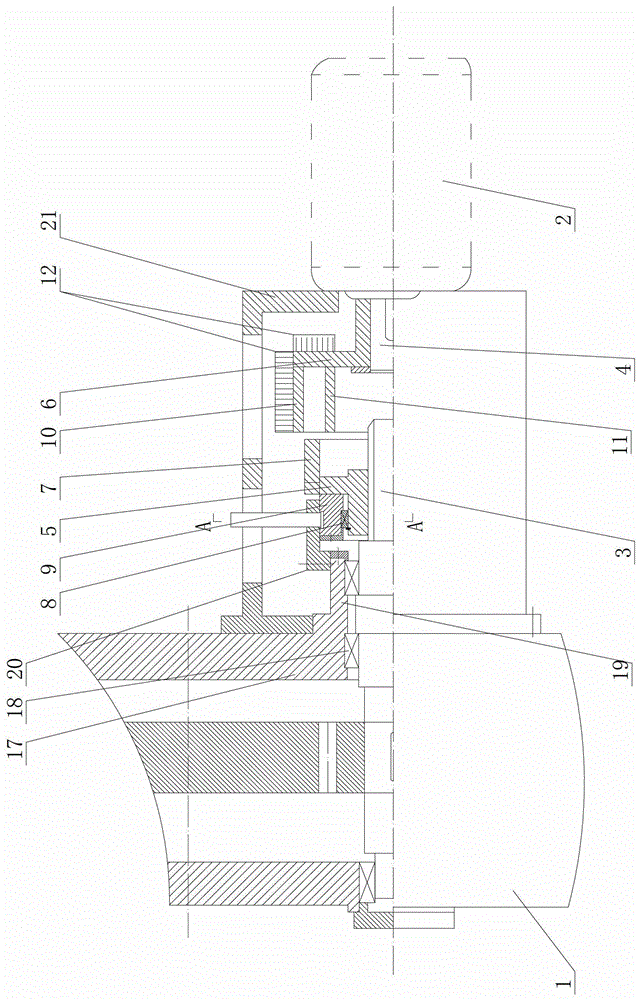
[0030] as attached figure 1 As shown, a speed-regulating reducer includes a reducer 1 and a motor 2, and the driving shaft 3 of the reducer 1 and the power shaft 4 of the motor 2 are connected through an electromagnetic speed-regulating mechanism, and the electromagnetic speed-regulating mechanism is used for Adjust the rotational speed of the driving shaft 3 of the reducer 1 .

[0031] In this embodiment, the above-mentioned electromagnetic speed regulating mechanism includes a sliding sleeve supporting ring 5 arranged outside the drive shaft 3 of the reducer 1 and a conductor ring supporting ring 6 arranged outside the power shaft 4 of the motor 2. The sliding sleeve supports An NdFeB magnet ring 7 is arranged on the ring 5, and the...


PUM


Abstract

The invention relates to a decelerator and especially relates to a speed regulation decelerator. The speed regulation decelerator comprises a decelerator body and a motor, wherein a driving shaft of the decelerator body is connected with a power shaft of the motor through an electromagnetic speed adjusting mechanism, and the electromagnetic speed adjusting mechanism is used for adjusting a rotation speed of the driving shaft of the decelerator body. The speed regulation decelerator can be directly connected with the motor; speed reduction and speed regulation of a load can be achieved; the speed regulation decelerator can be widely applied to operating environments with load characteristic requirements of a water pump, a blower fan, and the like; a rotation speed of the motor varies according to change in load; and energy can be saved by up to 60%.

Description

technical field [0001] The invention relates to a reducer, in particular to a speed-adjusting reducer. Background technique [0002] The workload of water pumps and fans often has non-constant power characteristics. The characteristic curve of the work shows that the increase or decrease of the motor power as the load speed increases or decreases becomes the most direct energy-saving method. [0003] In industrial and mining enterprises, most of the motors with load characteristics similar to those of fans and water pumps cannot directly realize speed regulation according to the change of load. Adjustments required for load changes. [0004] There is no suitable motor to be used directly to meet the requirements of the load curve, so frequency conversion is often used. Contents of the invention [0005] In order to solve the problems in the prior art, the present invention provides a speed-adjustable reducer, which is directly connected to an adjustable-speed reducer to ...

Claims


Application Information

Patent Timeline
Patent Type & Authority Patents(China)
IPC IPC(8): H02K51/00
Inventor 柳志明
Owner TIANJIN JIXUAN ENERY SAVING TECH CO LTD
Why Eureka
Try Eureka