Method and device for controlling power
A technology of power control and leveling, applied in the field of communication, can solve problems such as lowering communication quality and co-frequency interference
- Summary
- Abstract
- Description
- Claims
- Application Information
AI Technical Summary
Problems solved by technology
Method used
Image

Examples
Embodiment 1
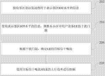
[0040] refer to figure 2 , shows a power control method of the present application, the method can be executed by the base station, and is used to control the uplink power of the UE in the cell managed by the base station, and the method includes:
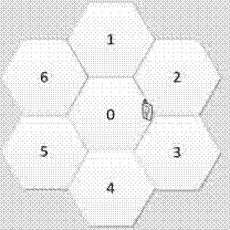
[0041] Step 202, receiving information indicating the level of interference and noise ratio (Interference over Thermal, IOT) of the neighboring cell sent by the base station of the neighboring cell;
[0042] For example, the base station of this cell receives the information indicating the IOT level of the neighboring cell sent by the base station of the neighboring cell through the X2 interface, and the information indicating the IOT level of the neighboring cell may be a newly added information element (Information Element, IE). Preferably, the information indicating the IOT level of the neighboring cell may be periodically sent by the base station of the neighboring cell.
[0043] In a specific implementation, the cell can als...
Embodiment 2
[0065] The present application also provides a method for controlling uplink power, which may be combined with the methods in the above-mentioned embodiments if there is no contradiction. The method described in this embodiment will be specifically described below.
[0066] The base station of each cell periodically measures the uplink IOT level of the cell, and sends the measurement result to the base station of the same-frequency neighbor cell through the X2 interface. The uplink IOT level can be added by adding a 2 in the X2 message loading information (LOADINFORMATION) Bit (bit) IE (such as ULInterferenceoverThermalLevel), as shown in Table 1 and Table 2.
[0067] Table 1
[0068]
[0069]
[0070] Table 2
[0071]
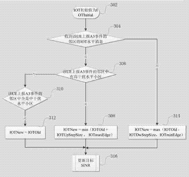
[0072] The IOT level (IOTLevel) indicates the average interference level of all uplink PRBs in the cell. As shown in the above table, the IOT level can be divided into three levels: high, medium and low. Among them, high interference corresponds t...
Embodiment 3
[0115] Such as Figure 5 As shown, the present application provides a power control device, which may be a base station, and the device may be used to implement the foregoing method embodiments, therefore, all the features in the foregoing method embodiments may be applied to this embodiment. Such as Figure 5 As shown, the device includes:
[0116] The receiving unit 502 is configured to receive the information indicating the IOT level of the neighboring cell sent by the neighboring cell base station;
[0117] An adjustment unit 504, configured to use the information indicating the IOT level of the neighboring cell to adjust the interference threshold of the UE in the cell;
[0118] A determining unit 506, configured to determine a target SINR of the UE according to the interference threshold;
[0119] The control unit 508 is configured to use the target SINR to control the uplink power of the UE.
[0120] In a preferred example of the embodiment of the present invention,...
PUM
 Abstract
Description
Claims
Application Information