Base station

Active Publication Date: 2016-06-23
KYOCERA CORP
View PDF6 Cites 7 Cited by
  • Summary
  • Abstract
  • Description
  • Claims
  • Application Information

AI Technical Summary

Benefits of technology

[0004]Although it is possible to reduce power consumption of a base station by stopping operation of a cell managed by the base station, it may decrease communication quality of a user termina

Problems solved by technology

Although it is possible to reduce power consumption of a base station by stopping operation of a cell managed by the

Method used


Image

  • Base station
  • Base station
  • Base station

Examples


embodiment

LTE System

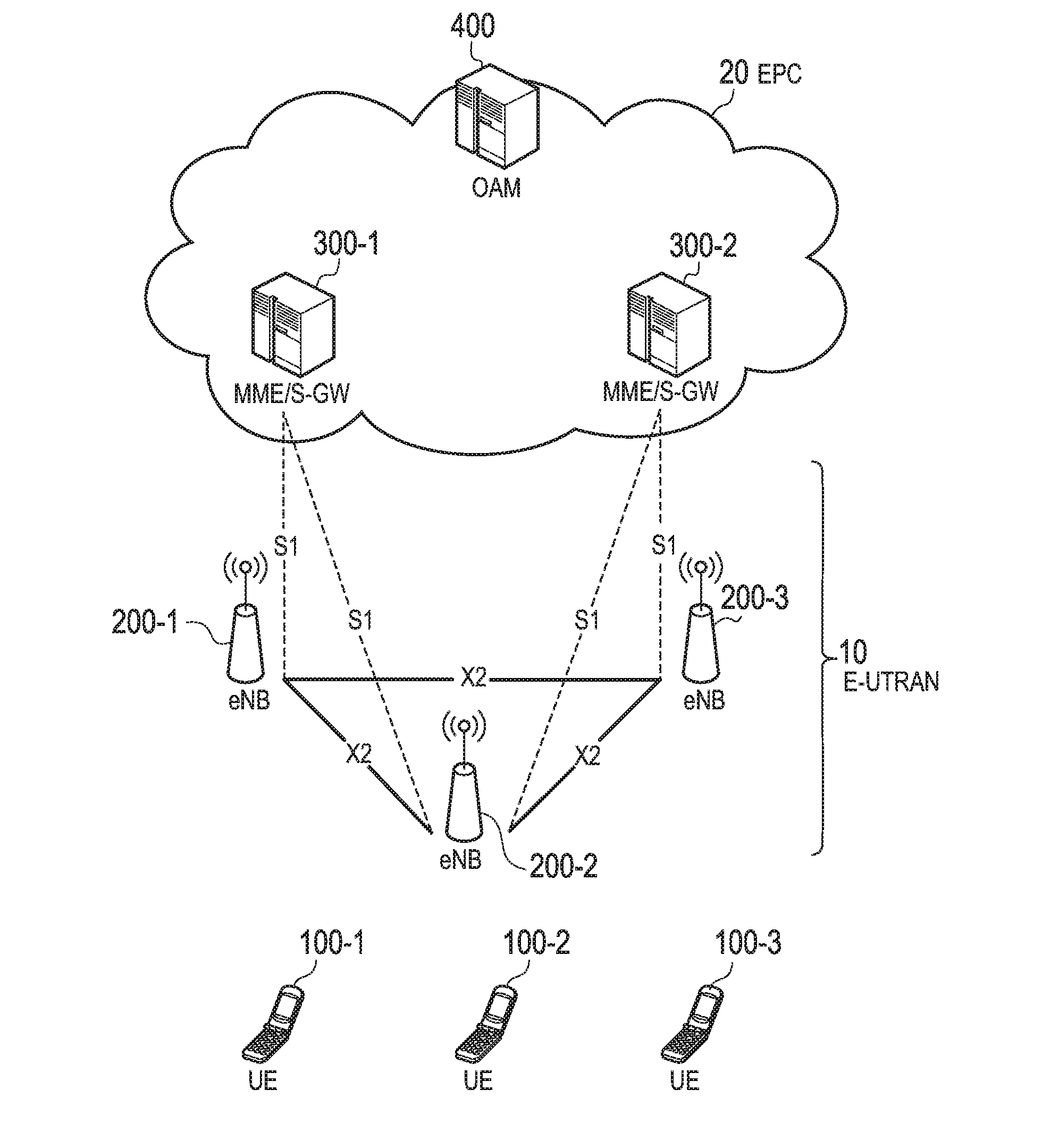
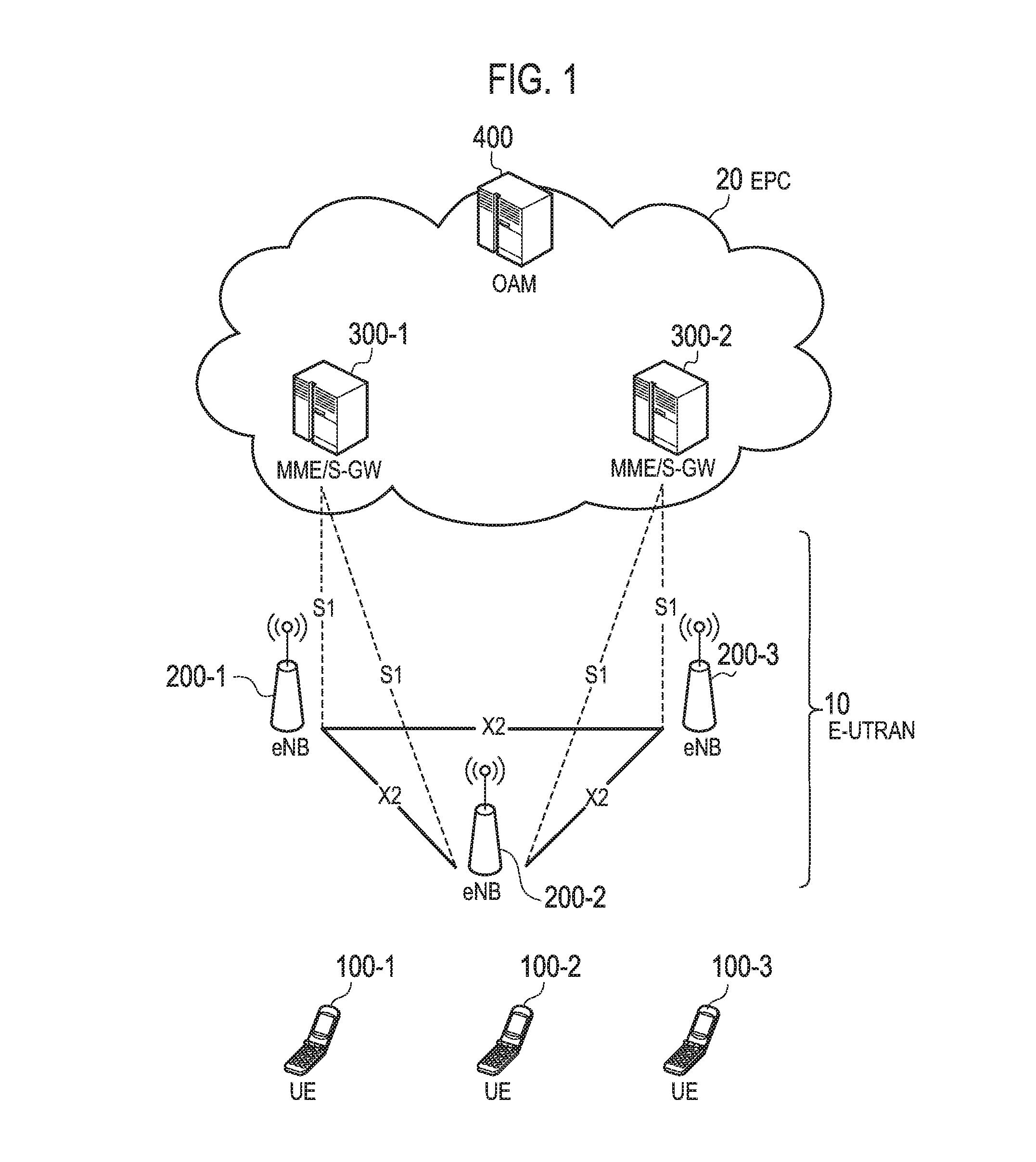
[0034]FIG. 1 is a configuration diagram of an LTE system according to the present embodiment.

[0035]As illustrated in FIG. 1, the LTE system includes a plurality of UEs (User Equipments) 100, an E-UTRAN (Evolved Universal Terrestrial Radio Access Network) 10, and an EPC (Evolved Packet Core) 20. The E-UTRAN and the EPC 20 constitute a network.

[0036]The UE 100 is a mobile radio communication device and performs radio communication with a cell (a serving cell) with which a connection is established. The UE 100 corresponds to the user terminal.

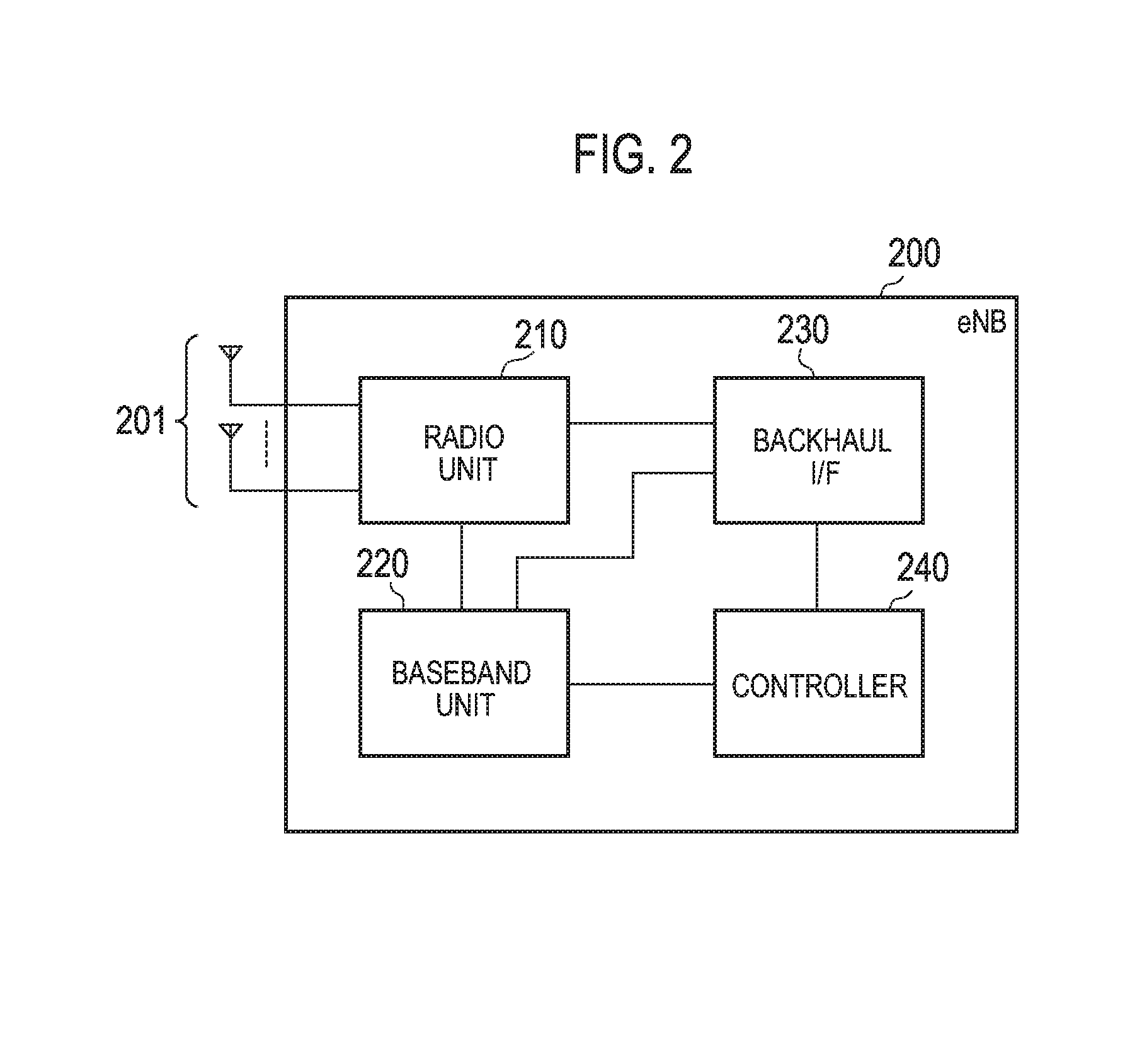
[0037]The E-UTRAN 10 includes a plurality of eNBs 200 (evolved Node-Bs). The eNB 200 corresponds to a base station. The eNB 200 controls a cell and performs radio communication with the UE 100 with which a connection with the cell is established.

[0038]It is noted that the “cell” is used as a term indicating a minimum unit of a radio communication area, and is also used as a term indicating a function of performing radio communication wit...


PUM


Abstract

A base station comprises: a controller configured to control, in a case another base station performs efficient operation by which a part of functions regarding communication with a user terminal is stopped, so that the part of functions is performed in the base station, in place of in the other base station, while the base station utilizes a radio unit and an antenna unit of the other base station.

Description

TECHNICAL FIELD[0001]The present invention relates to a base station used in a mobile communication system.BACKGROUND ART[0002]According to 3GPP (3rd Generation Partnership Project), which is a project aiming to standardize a mobile communication system, a technology for energy saving, which reduces power consumption of a base station, has been introduced (for example, see Non Patent Document 1). For example, by stopping operation of a cell managed by a base station, for example, in the nighttime when communication traffic is less, it is possible to reduce power consumption of the base station.PRIOR ART DOCUMENTNon-Patent Document[0003]Non Patent Document 1: 3GPP Technical Specification “TS36.300 V11.6.0” July, 2013SUMMARY OF THE INVENTION[0004]Although it is possible to reduce power consumption of a base station by stopping operation of a cell managed by the base station, it may decrease communication quality of a user terminal which establishes a connection with the cell. Therefor...

Claims


Application Information

Patent Timeline
IPC IPC(8): H04W36/08H04W52/02
CPCH04W52/0206H04W36/08Y02D30/70
Inventor FUKUTA, NORIYOSHIFUJISHIRO, MASATOYAMAZAKI, CHIHARUADACHI, HIROYUKI
Owner KYOCERA CORP
Why Eureka
Try Eureka