
Operating system for circuit boards

An operating system and circuit substrate technology, which is applied in the direction of assembling printed circuits, electrical components, and electrical components with electrical components. Maintenance-friendly effect

Active Publication Date: 2017-05-03
SHANDONG RIFA TEXTILE MACHINERY
View PDF3 Cites 0 Cited by
  • Summary
  • Abstract
  • Description
  • Claims
  • Application Information

AI Technical Summary

Problems solved by technology

On such an installation line, space utilization is limited, and it is desirable to have a compact circuit board operation system

Method used


Image

  • Operating system for circuit boards
  • Operating system for circuit boards
  • Operating system for circuit boards

Examples


Embodiment 1

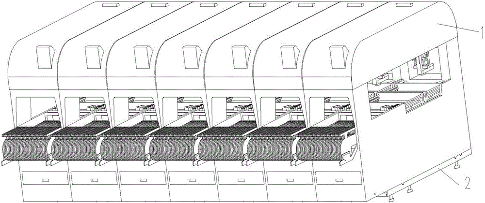
[0041] figure 1 Shown is a production line composed of a plurality of circuit substrate operation systems of the present invention. Each circuit substrate operation system includes the upper module body 1 and the bottom adjustment platform 2. Multiple devices are connected together to form a production line. Minimize the space occupancy. In actual production, the adjustment platform 2 is fixed, and only the module body 1 is adjusted, or the positions of the module bodies 1 are exchanged, and different types of module bodies are exchanged. The present invention is also applicable to High-speed module body and multi-function module body.

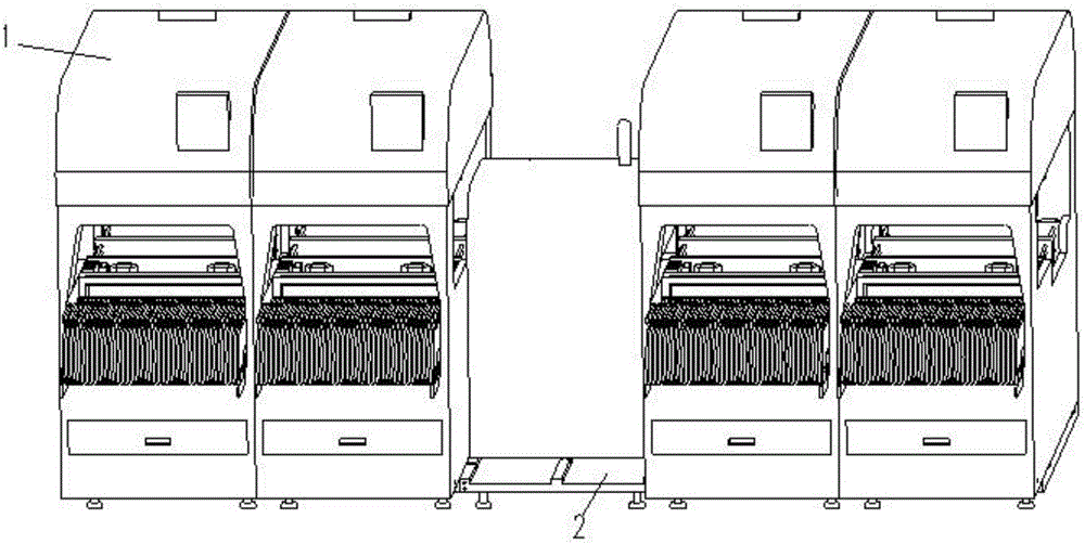
[0042] figure 2 Indicates that after one of the module bodies 1 has a fault problem, the faulty module body 1 can be pulled out, and the adjustment platform 2 is kept in place, and the substrate transmission system, Such as the schematic diagram of the production line behind the docking station. Generally, when a single module body 1 in t...

Embodiment 2

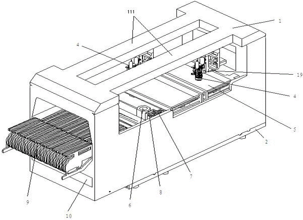
[0053] Figure 14 What is shown is another embodiment of the present invention, which is a multi-functional circuit substrate operation system. The circuit substrate operation system includes a module body 1 and an adjustment platform 2. The module body 1 adopts a single beam and a single paste The module body 1 includes a single beam 111, a multifunctional mounting head 45, a reference camera recognition system 19, a second platform support 46, a substrate transmission system 5, a component camera recognition system 6, a suction Nozzle replacement system 7, waste discarding system 8, and components supply system 9, waste bin 10 for containing waste belt, single crossbeam 111 is connected with the bottom of second platform support 46 and moves along the single crossbeam guide rail, on the second platform support 46 It is equipped with a multi-functional mounting head 45 and a reference camera recognition system 10, and the rest of the structure refers to Embodiment 1, and will...


PUM


Abstract

The invention discloses an operation system for a circuit substrate. The operation system for the circuit substrate comprises a module body and an adjusting platform. The module body comprises a module support on the upper portion and a base on the lower portion, wherein the module support and the base are connected with each other. A cross beam in the front and back direction is arranged on the upper portion of the module support. The bottom of the base is connected with the adjusting platform. A high-speed mounted work head and a datum point camera recognition system of the high-speed mounted work head are arranged below the cross beam. The high-speed mounted work head is connected with a mounted work head driving mechanism. A component supply system and a substrate delivery system are sequentially arranged on the upper portion of the base from front to back. A suction nozzle replacement system, a component camera recognition system and a waste discarding system are arranged between the component supply system and the substrate delivery system. The operation system for the circuit substrate is compact in structure, high in adaptability, convenient to operate and maintain, low in use cost and maintenance cost, high in safety and reliability, and capable of realizing high-speed mounting.

Description

technical field [0001] The invention belongs to the technical field of mechanical automation, and in particular relates to a circuit substrate operating system for mounting electronic components. Background technique [0002] The circuit substrate operation system is the most important part of the SMT production line. In order to maintain the accuracy and speed of its placement, it is necessary to carry out regular maintenance and maintenance on all parts of the equipment. It is difficult to operate the circuit substrate operation system, especially some systems that are generally located in the innermost part of the machine, due to space constraints. The traditional operating system for circuit substrates requires personnel to lean in to operate after opening the cover door, which is not only inconvenient but also dangerous. It is recorded in the published patent documents of Japan that for the designed modular equipment, the method of pulling out the whole module is adopt...

Claims


Application Information

Patent Timeline
Patent Type & Authority Patents(China)
IPC IPC(8): H05K13/04H05K3/30
Inventor 李子军孙宇丁士新祁玉斌王建岭
Owner SHANDONG RIFA TEXTILE MACHINERY
Learn More