
Fallopian tube recanalization body position rack

A technology for fallopian tubes and body positions, which is applied in patient positioning for diagnosis, medical science, surgery, etc. It can solve problems such as inability to adjust, inability to adjust the size, and no good solution, and achieve the effect of convenient adjustment

Inactive Publication Date: 2014-07-30
SHANDONG UNIV QILU HOSPITAL
View PDF5 Cites 0 Cited by
  • Summary
  • Abstract
  • Description
  • Claims
  • Application Information

AI Technical Summary

Problems solved by technology

During the treatment process, patients need to use their lithotomy position to carry out interventional diagnosis and treatment under the guidance of X-rays. However, since ordinary catheter beds do not have lithotomy position stands, it is difficult for patients to take lithotomy positions for a long time. If a position stand is installed on the catheter bed, It will also affect the intraoperative operation and X-ray machine operation of other non-intervention patients in this position. In the prior art, most of the lithotomy body positions are installed on the X-ray catheter bed. One is to affect the operation of other operations, and the other is to replace the machine , it is necessary to re-order and install the lithotomy position frame, which is not only time-consuming and labor-intensive but also costly
In addition, the existing body position frame is installed on the machine, and the size cannot be adjusted, and it cannot be conveniently adjusted according to the characteristics of each person
[0003] Currently, there is no good solution

Method used


Image

  • Fallopian tube recanalization body position rack
  • Fallopian tube recanalization body position rack
  • Fallopian tube recanalization body position rack

Examples


Embodiment Construction

[0021] Attached below figure 1 to attach Figure 6 The present invention is described further:

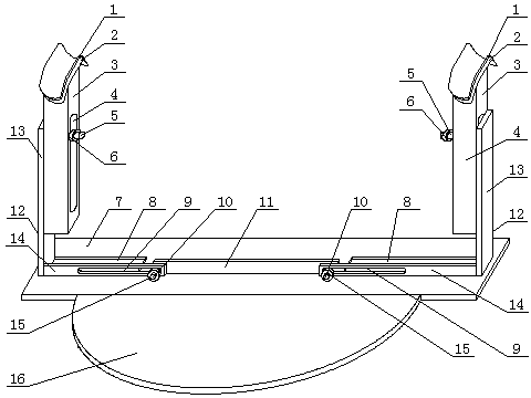
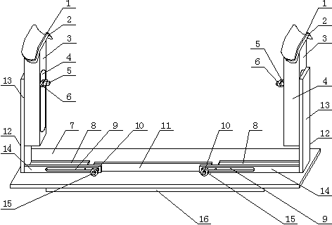
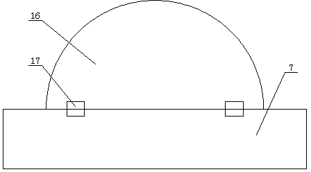
[0022] A fallopian tube recanalization position frame, comprising a base 7 and a popliteal fossa support device, the popliteal fossa support device comprising two popliteal fossa support plates 2, two vertical supports 3 and two horizontal supports 12, the popliteal fossa support plate 2 Fixed on the top of the vertical support 3, the vertical support 3 is movably arranged on the horizontal support 12, and can move up and down in the vertical direction; the base 7 is provided with two symmetrical chute 8, and the chute 8 is respectively placed There is a horizontal support 12, and a vertical plate 11 is arranged between the two chutes 8, and one end of the horizontal support 12 is movably arranged on the vertical plate 11, and can move left and right along the horizontal direction; the front end of the base 7 passes through the hinge 17 A pressing plate 16 is fixed.

[0023] In ...


PUM


Abstract

The invention relates to medical auxiliary machines, particularly to a fallopian tube recanalization body position rack. The fallopian tube recanalization body position rack comprises a base and a popliteal fossa support device, whereinthe popliteal fossa support device comprises two popliteal fossa supporting plates, two vertical brackets and two horizontal brackets; the popliteal fossa support plates are fixed tothe tops of the vertical brackets, and the vertical brackets capable of moving up and down inthe vertical direction are movably arranged on the horizontal brackets; two symmetric sliding chutes are formed in the base, the horizontal brackets are positioned in the sliding chutes respectively, a vertical plate is arranged between the sliding chutes, one end of each horizontal bracket is movably arranged on the vertical plate, and the horizontal bracket can move left and right in the horizontal direction; a pressure plate is fixed tothe front end of the base through hinges. The fallopian tube recanalization body position rack is positioned under a patient body when in need, the treatment to patients in other types on a duct bed cannot be influenced, the operation of a machine cannot be influenced, and the fallopian tube recanalization body position rack can provide convenience for the application of the intervention diagnosis and treatment tothe fallopian tube recanalization patient.

Description

technical field [0001] The invention relates to a medical auxiliary machine, in particular to a fallopian tube recanalization position stand. Background technique [0002] The gynecological bed is essential in clinical obstetrics and gynecology. Interventional tubal recanalization is a minimally invasive diagnosis and treatment of tubal obstruction diseases under the guidance of X-rays and using catheter guide wire technology. safe and effective treatment. During the treatment process, patients need to use their lithotomy position to carry out interventional diagnosis and treatment under the guidance of X-rays. However, since ordinary catheter beds do not have lithotomy position stands, it is difficult for patients to take lithotomy positions for a long time. If a position stand is installed on the catheter bed, It will also affect the intraoperative operation and X-ray machine operation of other non-intervention patients in this position. In the prior art, most of the lit...

Claims


Application Information

Patent Timeline
Patent Type & Authority Applications(China)
IPC IPC(8): A61G13/12A61B6/04
Inventor 李彩霞张静孙向阳张凯
Owner SHANDONG UNIV QILU HOSPITAL
Learn More