Foil plate conical element variable blank holder force deep drawing-blanking composite forming device and method

A technology of variable blank holder force and composite forming, applied in forming tools, metal processing equipment, manufacturing tools, etc., can solve the problems of types of materials that are easy to pollute the environment, insufficient process stability, long processing cycles, etc., to reduce wall thickness and reduce The effect of thinning, improving the drawing ratio, and improving work efficiency

Active Publication Date: 2014-07-30
HARBIN INST OF TECH
View PDF9 Cites 5 Cited by
  • Summary
  • Abstract
  • Description
  • Claims
  • Application Information

AI Technical Summary

Problems solved by technology

[0003] In order to solve the problems of long processing cycle, high cost, insufficient process stability, easy pollution of the environment and limited material types in the electroplating method of the existing foil plate conical shell parts, the present invention proposes a foil plate conical shell Device and method for variable blank-holding force deep drawing-blanking compound forming

Method used


Image

  • Foil plate conical element variable blank holder force deep drawing-blanking composite forming device and method
  • Foil plate conical element variable blank holder force deep drawing-blanking composite forming device and method
  • Foil plate conical element variable blank holder force deep drawing-blanking composite forming device and method

Examples


specific Embodiment approach 1

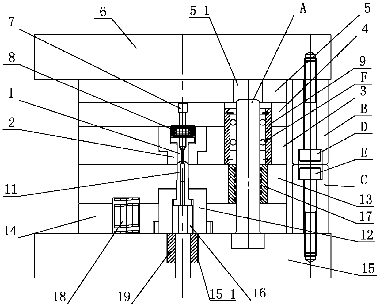
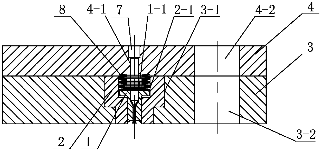
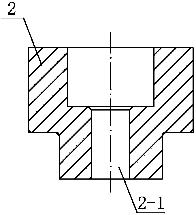
[0033] Specific implementation mode one: combine Figure 1 to Figure 11 Describe this embodiment, this embodiment includes upper mold, lower mold, guide post A, upper limit body B, lower limit body C, upper bolt D and lower bolt E, upper mold includes upper die 1, upper die fixing block 2. Upper binder ring 3, upper die fixing plate 4, upper template 5, upper die seat 6, punch 7, first spring 8 and upper die guide sleeve 9, upper and lower end surfaces of upper binder ring 3 are provided with The mounting hole 3-1 of the upper die fixing block and the first hole 3-2 of the guide sleeve, the upper die fixing block 2 is embedded in the mounting hole 3-1 of the upper die fixing block, the upper and lower end faces of the upper die fixing block 2 There is an upper die mounting hole 2-1, see image 3 , the upper die 1 is set in the upper die mounting hole 2-1, and the upper die 1 is provided with a punch hole 1-1 along the upper and lower end faces, see Figure 4 , the punch hole...

specific Embodiment approach 2

[0034] Specific implementation mode two: combination figure 1 This embodiment is described. The difference between this embodiment and the first embodiment is that it also adds several balls F, and several balls F are arranged between the guide post A and the upper die guide sleeve 9 . The ball E plays a supporting role. Other components and connections are the same as those in the first embodiment.

specific Embodiment approach 3

[0035] Specific implementation mode three: combination figure 1 Describe this embodiment, the difference between this embodiment and the specific embodiment one or two is that it also has a second spring 18, the lower end surface of the lower binder ring 13 is provided with a blind hole 13-4, and the lower punch fixing plate 14 There is a second spring installation hole 14-3 facing the blind hole 13-4, and the second spring 18 is installed in the blind hole 13-4 and the second spring installation hole 14-3. The second spring 18 plays a role in providing force for the blank holder in the later stage of deep drawing, and in addition, provides force for the blank holder during blanking. Other compositions and connections are the same as those in Embodiment 1 or 2.


PUM

PropertyMeasurementUnit
Movement speedaaaaaaaaaa
Diameteraaaaaaaaaa

Abstract

The invention provides a foil plate conical element variable blank holder force deep drawing-blanking composite forming device and a foil plate conical element variable blank holder force deep drawing-blanking composite forming method, and relates to a foil plate conical element precise micro punching forming device and a foil plate conical element precise micro punching forming method for solving the problems that the existing foil plate conical casing part adopts an electroplating method, the process stability defect exists, the environment can be easily polluted, and the material kinds are limited. The device is characterized in that an upper mold and a lower mold are in vertical arrangement, an upper female mold and a lower male mold are in vertical right aligned arrangement, the conical surface of the lower male mold arranged at the upper end of the lower male mold is anastomotic with the conical surface of a second conical hole section arranged on the upper female mold, an annular lower flange edge arranged at the upper end of the lower male mold is anastomotic with an annular upper flange edge arranged on the upper female mold, the length of each of the annular lower flange edge and the annular upper flange edge is 30 micrometers, and a guide post is arranged in an upper mold guide sleeve, a lower mold guide sleeve and a lower guide post hole. The method comprises the steps of blank-holding-free deep drawing, blank holding deep drawing and shape correction, center micropore blanking, conical element bottom outer circle blanking and demolding, and a foil plate conical element is obtained. The device and the method provided by the invention are used for foil plate conical casing part forming.

Description

technical field [0001] The invention relates to a precision micro-punching forming device and method for a foil plate cone-shaped part, in particular to a variable blank-holding force deep drawing-punching composite forming device and method for a foil plate cone-shaped part. Background technique [0002] Foil tapered (thickness less than 50 microns) housing parts are widely used in the microelectronics industry. However, due to the small thickness and complex shape of the plate, it is very difficult to manufacture. Existing processing foil shell parts: first process a mold, then use electroplating process to plate the material on the mold, and corrode the mold after the material is formed, that is, complete the forming of foil shell parts; this method is only Limited to nickel alloy or pure gold materials, this method not only has the problems of insufficient process stability, long processing cycle, and high cost, but also easily pollutes the environment. Therefore, it i...

Claims


Application Information

Patent Timeline
IPC IPC(8): B21D37/10B21D33/00
Inventor 王春举单德彬郭斌程思锐张博徐杰
Owner HARBIN INST OF TECH
Why Eureka
Try Eureka