High-reliability hydraulic ejector

A hydraulic injector, reliable technology, applied in the direction of mining fluid, wellbore/well components, earthwork drilling and production, etc., can solve problems such as tool failure, tool external damage, nozzle and pressure cap drop, etc., to prevent drop , Improve the reliability of use and the efficiency of construction, and the effect of increasing the number of construction sections

Active Publication Date: 2014-07-30
西安迈卓能源科技有限公司
7 Cites 2 Cited by

AI-Extracted Technical Summary

Problems solved by technology

[0002] During hydraulic jet fracturing operations in oil and gas fields, ultra-high-speed water jets are used to drive abrasives to carry out perforation. Damage, severe cases may even lead to the drop of the nozzl...

Method used

Described gland 9, liner 11 adopt wear-resisting and anti-erosion material cemented carbide YG15 to manufacture, have very high anti-erosion property, can prevent the erosion that high-speed water jet produces to the inside of water power injector like this , It can also prevent the high-speed water jet backsplash from damaging the exterior of the water jet, not only prevent the nozzle from falling, but also effectively protect the body, improve the reliability of use, and prolong th...

Abstract

The invention discloses a high-reliability hydraulic ejector, which is characterized in that the body of the hydraulic ejector is provided with a pressing cap hole, a nozzle is positioned in a pressing cap, and the pressing cap is fixedly arranged on the pressing cap hole. The inner wall of the body is provided with an annular groove, the annular groove is communicated with the lower end opening of the body, and a lining is inserted into the annular groove from the lower end opening of the body. The lower end surfaces of the body and the lining are both provided with corresponding positioning grooves, positioning blocks are inserted into the positioning grooves so as to position the lining on the body in the circumferential direction, thus a jet hole in the lining is aligned with the nozzle, and the diameter of the jet hole is larger than the inside diameter of the nozzle and is smaller than the outer diameter of the nozzle. The lower end opening of the body is connected with a lower connector, and the positioning blocks are restricted in the positioning grooves by virtue of the inner end surface of the lower connector. The outer end surface of the pressing cap is fixedly provided with a gland. By arranging the lining made of a special wear-resistant material and the gland, inner scouring and backwashing problems of the hydraulic ejector in the oil and gas field on-site construction process can be effectively solved, the use reliability of the hydraulic ejection tool is greatly improved, and the number of construction sections is greatly increased.

Application Domain

Technology Topic

Image

  • High-reliability hydraulic ejector
  • High-reliability hydraulic ejector
  • High-reliability hydraulic ejector

Examples

  • Experimental program(1)

Example Embodiment

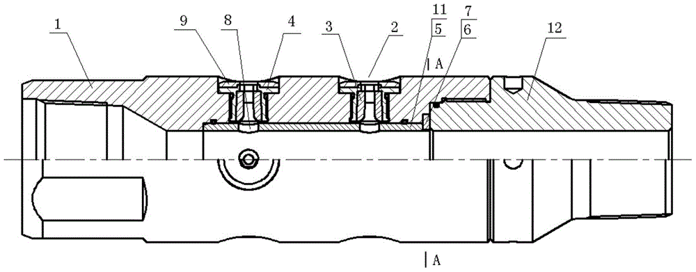
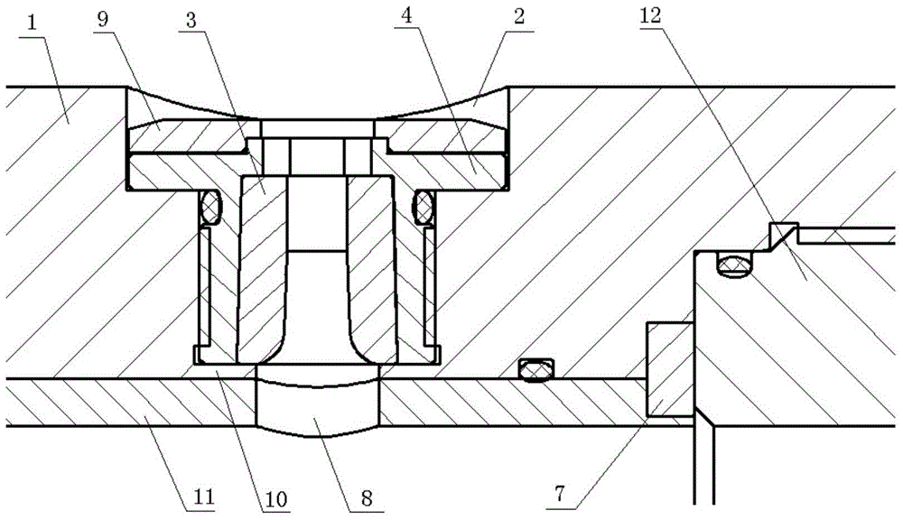
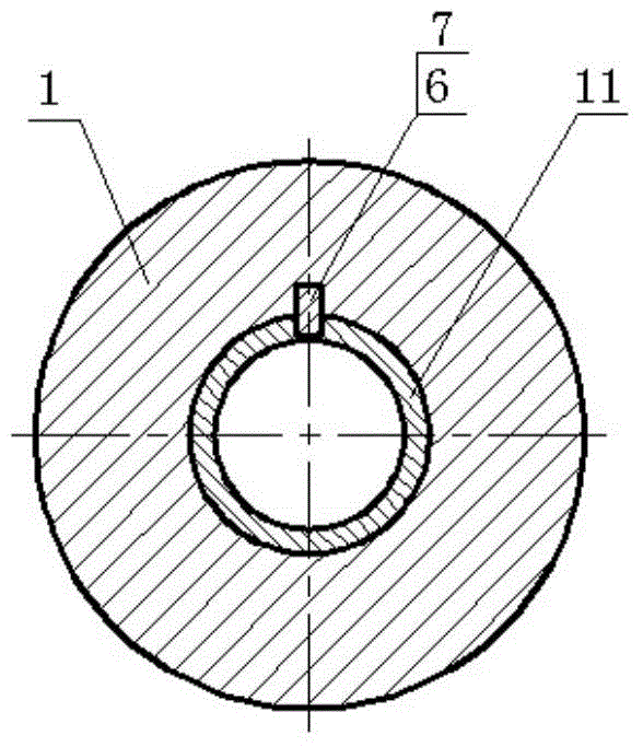
[0013] Combine below figure 1 , 2 , 3 describes an embodiment of the present invention.
[0014] A high-reliability water jet, comprising a body 1 with a pressure cap hole 2 formed on the body 1, the pressure cap hole 2 is a stepped shape with a large outside and a small inside, and the small hole at the inner end is an internal threaded hole The pressure cap 4 is a stepped shape that matches the shape of the pressure cap hole 2, and its inner hole is a stepped shape with a small outside and a large inside. The nozzle 3 is inserted into the large hole at the inner end, and the small hole at the outer end is an inner hexagon, Used for loading and unloading the pressure cap 4; the pressure cap 4 is installed in the internal threaded hole at the inner end of the pressure cap hole 2 through the external thread on the outer wall of the small end; the pressure cap 4 is brazed with a pressure cap on the outer end surface 9, and the pressure cover 9 is clamped on the boss at the center of the outer end of the pressure cap 4, and the center hole is aligned with the small hole at the outer end of the pressure cap 4.
[0015] An annular groove 5 is formed on the inner wall of the body 1, and the annular groove 5 penetrates the lower port of the body 1, and the bushing 11 is inserted into the annular groove 5 from the lower port of the body 1; Corresponding positioning grooves 6 are formed on the lower end surfaces of the body 1 and the bushing 11, and the positioning block 7 is inserted into the positioning groove 6 to position the bushing 11 on the body 1 circumferentially, so that the jet holes on the bushing 11 8 is aligned with the nozzle 3, and the diameter of the jet hole 8 is larger than the inner diameter of the nozzle 3 and smaller than the outer diameter of the nozzle 3; the lower port of the body 1 is threadedly connected with a lower joint 12, and is positioned by the inner end surface of the lower joint 12 The block 7 is blocked in the positioning groove 6;
[0016] The body 1 has an annular shoulder 10 at the inner end surface of the cap hole 2, and the center hole of the annular shoulder 10 faces the jet hole 8. The annular shoulder 10 and the bushing 11 simultaneously have the effect of preventing the nozzle from falling. The pressure cap 4 and the pressure cap hole 2, the bushing 11 and the body 1, and the lower joint 12 and the body 1 are all sealed by sealing rings to prevent pressure leakage.
[0017] The gland 9 and the bushing 11 are made of hard alloy YG15, which is a wear-resistant and erosion-resistant material, which has high erosion resistance. This can prevent the high-speed water jet from eroding the inside of the hydraulic ejector. It prevents the high-speed water jet back splash from damaging the exterior of the water jet, which not only prevents the nozzle from falling, but also effectively protects the body, improves the reliability of use, and extends the service life.
[0018] The above-mentioned embodiments are only preferred embodiments of the present invention and are not used to limit the scope of implementation of the present invention. Therefore, all equivalent changes made with the content of the claims of the present invention shall be included in the scope of the claims of the present invention.

PUM

no PUM

Description & Claims & Application Information

We can also present the details of the Description, Claims and Application information to help users get a comprehensive understanding of the technical details of the patent, such as background art, summary of invention, brief description of drawings, description of embodiments, and other original content. On the other hand, users can also determine the specific scope of protection of the technology through the list of claims; as well as understand the changes in the life cycle of the technology with the presentation of the patent timeline. Login to view more.

Similar technology patents

Classification and recommendation of technical efficacy words

Why Eureka
Try Eureka