Curved liquid crystal panel structure

A liquid crystal panel, curved surface technology, applied in nonlinear optics, instruments, optics, etc., can solve the problem of inconsistent light transmittance and response time in the middle area and both sides, blurred images displayed on the curved liquid crystal panel, and uneven thickness distribution of the liquid crystal layer. Equalize the problem to achieve the effect of improving optical taste, consistent light transmittance and response time, and simple structure

Active Publication Date: 2014-07-30
TCL CHINA STAR OPTOELECTRONICS TECH CO LTD
View PDF5 Cites 59 Cited by
  • Summary
  • Abstract
  • Description
  • Claims
  • Application Information

AI Technical Summary

Problems solved by technology

The spacer 300 is arranged between the TFT substrate 100 and the CF substrate 200 in the manner of equal height, equal density, equal CD (Critical Dimension) value, that is, equal size. The curved TFT substrate 100 and the CF substrate 200 will slide relative to each other, and the curved liquid crystal panel will generate left and right sliding stress with the center as the base point, and the stress will gradually decrease from the center to both sides. At the same time, the TFT substrate 100 The stress of mutual extrusion with the CF substrate 200 also gradually decreases from the center to both sides, and the stress on the middle area of ​​the curved liquid crystal panel is greater than that on the two sides, but the spacer 300 has the same height, the same density, and the same CD value. The method is set to cause the deformation of the middle area of ​​the curved liquid crystal panel to be greater than the deformation of the two sides, so that the cell thickness of the middle area is smaller than that of the two sides, resulting in uneven distribution of liquid crystal layer thickness, and the difference between the middle area and the two sides The light transmittance and response time are inconsistent, resulting in blurred images displayed on the curved LCD panel and a decrease in optical quality

Method used


Image

  • Curved liquid crystal panel structure
  • Curved liquid crystal panel structure
  • Curved liquid crystal panel structure

Examples


Embodiment Construction

[0028] In order to further illustrate the technical means adopted by the present invention and its effects, the following describes in detail in conjunction with preferred embodiments of the present invention and accompanying drawings.

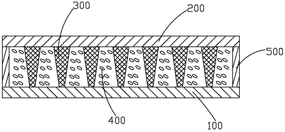
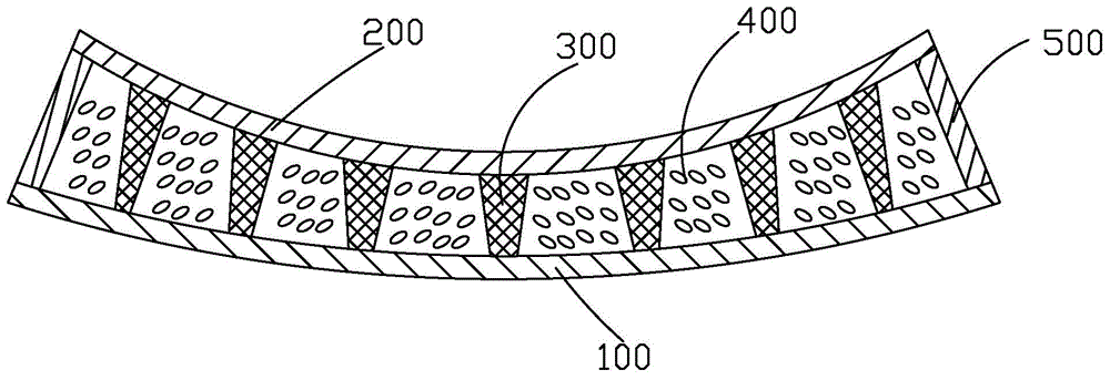
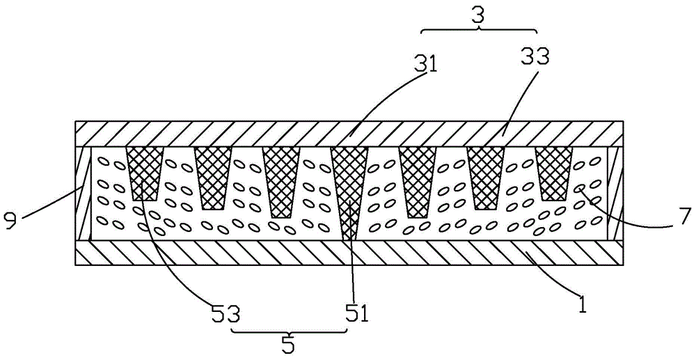
[0029] see image 3 , Figure 4 , which is the first preferred embodiment of a curved liquid crystal panel structure in the present invention. The curved liquid crystal panel structure includes: a TFT substrate 1, a CF substrate 3 corresponding to the TFT substrate 1, a spacer 5 arranged between the TFT substrate 1 and the CF substrate 3, and a spacer 5 arranged between the TFT substrate 1 and the CF substrate 3. The liquid crystal layer 7 and the sealant layer 9 arranged between the TFT substrate 1 and the CF substrate 3 and located at the edge. The TFT substrate 1 is used to drive the liquid crystal molecules in the liquid crystal layer 7 to deflect, so as to select the light transmitted through the curved liquid crystal panel, the CF subs...


PUM


Abstract

The invention provides a curved liquid crystal panel structure, which comprises a TFT base plate (1), a CF base plate (3), spacing objects (5), a liquid crystal layer (7) and a sealing glue layer (9), wherein the CF base plate (3) is in arrangement corresponding to the TFT base plate, the spacing objects (5) are arranged between the TFT base plate (1) and the CF base plate (3), the liquid crystal layer (7) is arranged between the TFT base plate (1) and the CF base plate (3), the sealing glue layer (9) is arranged between the TFT base plate (1) and the CF base plate (3) and is positioned at the edge, in the bending direction of a curved liquid crystal panel, the CF base plate (3) is provided with a middle region (31) and two side regions (33) positioned at two sides of the middle region, the stress born by the middle region (31) is greater than that born by the two side regions (33), and the spacing object (51) positioned in the middle region (51) is set to be capable of bearing higher stress than the spacing object (53) positioned at two side regions (33), so the equal gap is maintained between the CF base plate (3) and the FT base plate (1), and the integral box thickness consistency of the curved liquid crystal panel is ensured.

Description

technical field [0001] The invention relates to the field of liquid crystal display, in particular to a curved liquid crystal panel structure. Background technique [0002] A liquid crystal display (Liquid Crystal Display, LCD) has many advantages such as a thin body, power saving, and no radiation, and has been widely used. Such as: LCD TV, mobile phone, personal digital assistant (PDA), digital camera, computer screen or laptop screen, etc. [0003] Generally, a liquid crystal display device includes a housing, a liquid crystal panel disposed in the housing, and a backlight module disposed in the housing. Among them, the structure of the liquid crystal panel is mainly composed of a thin film transistor array substrate (Thin Film Transistor Array Substrate, TFT Array Substrate), a color filter substrate (Color Filter, CF), and a liquid crystal layer ( Liquid Crystal Layer), its working principle is to control the rotation of liquid crystal molecules in the liquid crystal ...

Claims


Application Information

Patent Timeline
Patent Type & Authority Applications(China)
IPC IPC(8): G02F1/1339
CPCG02F1/133305G02F1/13394G02F1/13396G02F1/133514G02F1/1339G02F1/1368
Inventor 吴川郭晋波罗时勋
Owner TCL CHINA STAR OPTOELECTRONICS TECH CO LTD
Why Eureka
Try Eureka