Display device and manufacturing method thereof

A technology for display devices and array substrates, applied in nonlinear optics, instruments, optics, etc., can solve the problems of increased difficulty in manufacturing process and circuit drive, different response time of liquid crystal in the transmission area, and increased difficulty of manufacturing process, etc., to achieve the goal of manufacturing process And the effect of simple circuit driving, lower driving voltage, and consistent box thickness

Active Publication Date: 2014-10-15
BOE TECH GRP CO LTD
View PDF4 Cites 0 Cited by
  • Summary
  • Abstract
  • Description
  • Claims
  • Application Information

AI Technical Summary

Problems solved by technology

However, different cell thicknesses will result in different liquid crystal response times in the transmissive and reflective regions, which will also increase the difficulty of the manufacturing process and increase the production cost.
In the prior art, there is also a structure of a single-cell thick transflective display device, and its research focuses on the use of different liquid crystal modes in the transmissive area and the reflective area, which makes the manufacturing process and circuit driving more difficult, and the production cost is greatly increased.

Method used


Image

  • Display device and manufacturing method thereof
  • Display device and manufacturing method thereof
  • Display device and manufacturing method thereof

Examples


Embodiment 1

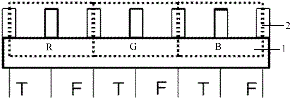
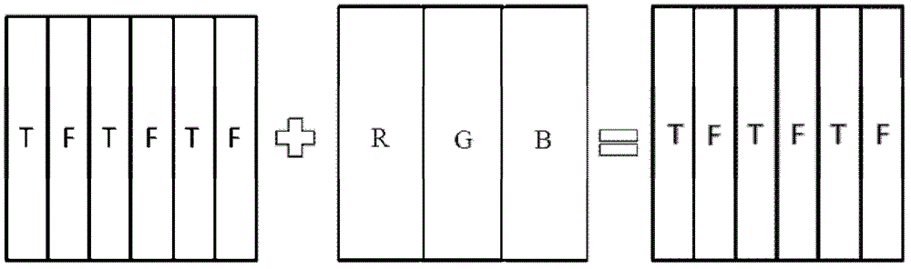
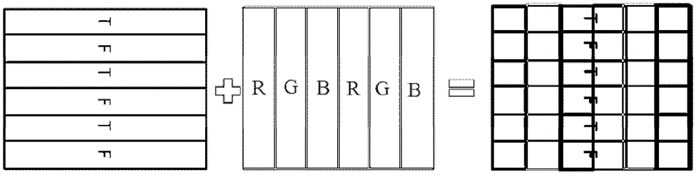
[0031] The display device provided in this embodiment includes a liquid crystal cell formed by pairing an array substrate and a color filter substrate, wherein wall-shaped electrodes arranged at intervals are formed on the array substrate, such as figure 1 As shown, the wall-shaped electrode 2 separates a row or a column of sub-pixels R or G or B on the color filter substrate, and divides each row or column of sub-pixels R or G or B into two rows or columns of sub-pixels, The areas where two rows or two columns of sub-sub-pixels are located respectively form a light transmission area T and a light reflection area F, thereby forming a plurality of adjacent grooves and walls corresponding to the transmission area T and reflection area F in the liquid crystal cell. The shaped electrode 2 is not only the separation of the transmissive area T and the reflective area F, but also serves as a signal electrode to provide a strong transverse electric field, and can also support the thick...

Embodiment 2

[0036] This embodiment provides a method for manufacturing the display device described in Embodiment 1, which includes the following processes:

[0037] First, wall-shaped electrodes are prepared on the array substrate.

[0038] Specifically, the photoresist material is coated on the array substrate, and photoetched through a mask to form wall-shaped electrodes arranged at intervals. The wall-shaped electrodes separate a row or a column of sub-pixels on the array substrate, and each row Or each column of sub-pixels is divided into two rows or two columns of sub-sub-pixels, and the regions where the two rows or two columns of sub-sub-pixels are located respectively form a light transmission area and a light reflection area arranged at intervals.

[0039] Secondly, screens are made in boxes.

[0040] Specifically, coating the frame sealant on the color filter substrate, curing the array substrate and the color filter substrate into boxes and cutting them into screens;

[0041...


PUM


Abstract

The invention discloses a display device, wherein a wall-shaped electrode is formed on an array substrate, and the wall-shaped electrode separates a row or a column of sub-pixels on a color filter substrate and divides each row or column of sub-pixels into two rows or two columns For the sub-sub-pixels, two rows or two columns of sub-sub-pixels respectively form a light transmission area and a reflection area, and the liquid crystal poured in the light transmission area and the light reflection area makes the light in the transmission area and the reflection area have the same optical path difference. The invention also discloses a manufacturing method of the display device. The present invention can realize the transmissive and reflective display of the display device, without interference from ambient light, strong visibility and energy saving; the thickness of the transmissive area and the reflective area are consistent, the influence of liquid crystal response time is small, and the process is simple; the wall-shaped electrode is adopted, With a high transverse electric field, the driving voltage can be significantly reduced; no compensation film or retarder in the box is required, and the cost is reduced; the transmission area and the reflection area are only different from the liquid crystal, the manufacturing process and circuit driving are simple, and the feasibility is strong.

Description

technical field [0001] The invention belongs to the field of display technology, in particular to a display device and a manufacturing method thereof. Background technique [0002] The transflective liquid crystal display has both the excellent reading performance of the reflective display in outdoor sunlight and the excellent reading performance of the fully transparent display in the dark and weak light environment, so it is widely used in aircraft display instruments, vehicle displays, high-end mobile phones , portable computers and other fields. [0003] The sub-pixels of the transflective liquid crystal display are composed of a transmission area and a reflection area. The transmission area uses a backlight to emit light, and the light only passes through the liquid crystal layer once, while the reflection area relies on reflecting the ambient light source to emit light. The light needs to pass through the liquid crystal layer twice. This makes the optical path differe...

Claims


Application Information

Patent Timeline
Patent Type & Authority Patents(China)
IPC IPC(8): G02F1/1343G02F1/1339G02F1/1341
CPCG02F1/1343G02F1/133514G02F1/1341G02F1/1335G02F1/133377G02F1/133516G02F1/134363G02F1/133555G02F1/1393
Inventor 赵伟利
Owner BOE TECH GRP CO LTD
Why Eureka
Try Eureka