A kind of printing plate-making equipment and plate-making method

A technology of equipment and printing plates, which is applied in the field of printing plate making equipment and plate making, can solve problems such as LED light-emitting units not being able to emit light normally, LED arrays not being used normally, blurred exposure graphic edges, etc., to achieve large-area one-time exposure and improve long-term Effect of plate cycle and ablation instability, reduced number of image transfers

Active Publication Date: 2015-11-04
十二秒融媒体(山东)有限公司
View PDF5 Cites 0 Cited by
  • Summary
  • Abstract
  • Description
  • Claims
  • Application Information

AI Technical Summary

Problems solved by technology

However, this technology has the following disadvantages: 1. The accuracy is not high. As we all know, LED lights are point light sources, and the array formed by LED lights is formed by a series of LED light-emitting units arranged at intervals. The light emitted by a single LED light is not a completely parallel beam. There is also scattered light in the interval between LED lamps, and the light of a single LED lamp spreads in the form of strong center and weak edge, especially when the distance between the LED lamp and the printing plate is large, the light of the LED lamp located at the edge of the image shines on the Halos are formed on the printing plate, which leads to blurred edges of the exposure pattern, resulting in a decrease in imaging accuracy; 2. High cost, LED arrays, especially UVLED lamps, usually use special semiconductor materials, and the semiconductor materials are processed by the overall photolithography of the wafer , usually grown by CVD method, the cost is extremely high; 3. Poor fault tolerance, easy to form bad spots in the LED array due to factors such as production and maintenance, that is, individual LED light-emitting units cannot emit light normally, and due to process limitations, it is difficult to replace individual LED particles , so that the whole LED array cannot be used normally
[0007] It can be seen that in the prior art, especially in the widely used CTP and CTcP plate-making processes, there are insurmountable technical obstacles in the existing technical level and solution ideas. Due to technical problems such as high cost, short equipment life cycle and high cost of consumables, it is urgent to change the design idea and provide a new generation of computer plate-making equipment with simple structure, easy maintenance and low plate-making cost

Method used


Image

  • A kind of printing plate-making equipment and plate-making method
  • A kind of printing plate-making equipment and plate-making method
  • A kind of printing plate-making equipment and plate-making method

Examples


Embodiment Construction

[0032] In order to make the technical scheme of the present invention and its technical effect clearer and clearer, the following is combined figure 1 —4 The specific implementation of the present invention will be further detailed. It should be understood that the following specific embodiments are only used to explain the present invention, but not to limit the present invention.

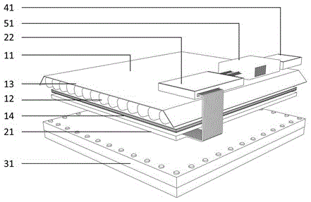
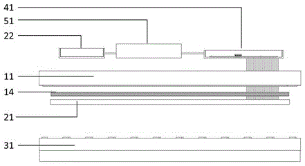
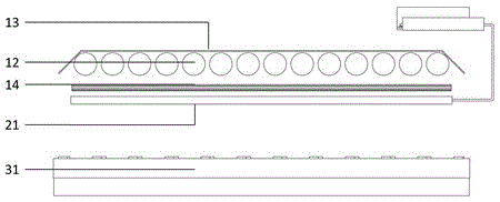
[0033] Such as figure 1 As shown, it is a perspective view of a printing plate making device in a specific embodiment. The printing plate-making equipment includes: an exposure device 11, a printing image imaging device 21, a printing plate bearing device 31, and a timing control device 41. Conventional components such as a power supply box 51 are well known in the art and will not be repeated.

[0034] In terms of overall structure, the exposure light source 11, the printing image imaging device 21, and the printing plate bearing device 31 are arranged coaxially in sequence to ensure the efficiency an...


PUM

PropertyMeasurementUnit
wavelengthaaaaaaaaaa

Abstract

The invention provides printing plate making equipment and a plate making method. The equipment comprises an exposure device, a print image imaging device, a printing plate carrying device and a timing control device, wherein the exposure device comprises an exposure light source and an exposure light source control device; the exposure light source, the print image imaging device and the printing plate carrying device are coaxially arranged in sequence; the exposure light source is used for irradiating light to cure a photosensitive material loaded on a printing plate; the print image imaging device is used for forming a target image to replace a film, wherein the target image masks the light from the exposure light source so that a corresponding exposure image is formed on the printing plate. Therefore, accurate plate making and accurate overprinting are achieved, a film making process is omitted, an environmentally friendly plate making process which reduces the production cost and environmental pollution is formed, and a variety of defects in the prior art, particularly in traditional plate making, CTP and CTcP plate making equipment and corresponding processes are solved.

Description

Technical field [0001] The invention belongs to the field of printing, and particularly relates to a printing plate making device and a plate making method. Background technique [0002] The plate-making process is an important step in the pre-press process. It plays a very important role in the entire printing process and has an extremely important impact on the color, tone and register of the printed matter. With the development of science and technology, the plate-making process has also continued to evolve, from traditional film plate making to wax-spray plate making, ink-jet plate making, to the widely used laser plate making, etc., with the development of computer technology, plate making process gradually Combining them, and continuously developing in the direction of high efficiency, environmental protection and low cost, thus forming the computer-to-plate technology. [0003] The so-called computer to plate (Computer to Plate, CTP for short) is to use a computer to digita...

Claims


Application Information

Patent Timeline
Patent Type & Authority Patents(China)
IPC IPC(8): G03F7/00G03F1/00B41C1/00
Inventor 杨涛
Owner 十二秒融媒体(山东)有限公司
Why Eureka
Try Eureka