
Ground wire special for middle switch cabinet

A grounding wire and switch cabinet technology, which is applied in the field of special grounding wires for central switch cabinets, can solve the problems of cumbersome, time-consuming and labor-intensive grounding for central cabinets, and grounding wires, and achieve clear grounding points, convenient use, and grounding good effect

Inactive Publication Date: 2014-07-30
STATE GRID CORP OF CHINA +1
View PDF9 Cites 4 Cited by
  • Summary
  • Abstract
  • Description
  • Claims
  • Application Information

AI Technical Summary

Problems solved by technology

[0005] One is to go to another switch cabinet that is in the standby state, open the cable room and seal the panel, and connect the grounding wire after the electric prod proves that there is no electricity, which causes the switch cabinet that needs to be repaired to not be connected. Ground wire, but the switchgear that should not be connected to the ground wire is connected to the ground wire, which may cause the switch to be closed with the ground wire, and the consequences are quite serious.
[0006] In addition, when connecting the ground wire in the cable room behind the central switch cabinet, the operator needs to drill to the side of the cabinet to connect the line, which is time-consuming and laborious
[0007] According to the analysis of some problems and difficulties encountered in the actual operation of substation operation and maintenance caused by the structure of 10kV and 35kV central cabinets, the special grounding wire for central switch cabinets of the present invention is developed without violating the "Safety Regulations". To improve the operation process of the on-duty personnel, and solve the current situation that the electrical inspection and grounding of the central cabinet is relatively cumbersome and has great potential safety hazards

Method used


Image

  • Ground wire special for middle switch cabinet
  • Ground wire special for middle switch cabinet

Examples


Embodiment Construction

[0019] The present invention will be further described below in conjunction with the accompanying drawings.

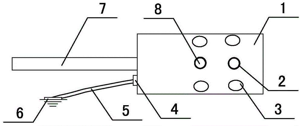
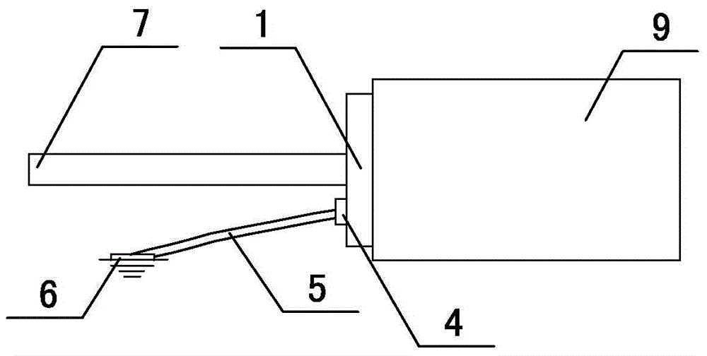
[0020] Such as Figure 1-2 As shown, the special grounding wire for the central switch cabinet of the present invention is composed of a grounding wire clip 6, an annealed grounding copper wire 5, an insulating operating rod 7 and a metal head, and a cylindrical aluminum metal head 1 is arranged on the top of the insulating operating rod 7. The insulating operating rod 7 is tightly crimped on the cylindrical aluminum metal head 1, and the cylindrical aluminum metal head 1 is ring-shaped and uniformly arranged with two rows of corresponding contact holes 2, and the inside of the contact hole 2 is provided with elastic metal ball contacts 8 , between the two contact holes 2 in each row is a fixing hole 3, the lower static contact 9 in the central switch cabinet is provided with a protrusion corresponding to the fixing hole 3, and the bottom of the cylindrical aluminum me...


PUM


Abstract

The invention relates to the technical field of power grid operation devices, in particular to a ground wire special for a middle switch cabinet. The ground wire special for the middle switch cabinet is composed of a ground wire clamp, a ground annealed copper wire, an insulating operating bar and a metal head, wherein the cylindrical aluminum metal head is arranged on the top of the insulating operating bar, the insulating operating bar is connected to the cylindrical aluminum metal head in a compact pressing mode, two rows of contact holes which are corresponding in position are annularly and evenly formed in the cylindrical aluminum metal head, elastic metal ball contacts are arranged in the contact holes, a fixing hole is formed between every two adjacent contact holes of each row, protrusions corresponding to the fixing holes are arranged in a lower static contact in the middle switch cabinet, a pressing connection position connected with the ground annealed copper wire is arranged at the bottom of the cylindrical aluminum metal head, the ground terminal of the ground wire special for the middle switch cabinet is connected with the ground wire clamp, and an electricity connection terminal is connected to the cylindrical aluminum metal head through the ground annealed copper wire. Compared with a fixed type ground wire, the ground wire special for the middle switch cabinet has the advantages of being more convenient to use, clearer in grounding point and higher in safety reliability.

Description

technical field [0001] The invention relates to the technical field of power grid operation equipment, in particular to a special grounding wire for a central switch cabinet. Background technique [0002] In the prior art, when the line is connected to the ground wire, it is necessary to remove the rear sealing plate of the cable room of the central switch cabinet, and use an electric test rod to conduct an electric test on the exposed part of the branch bus in the cabinet. The cable room behind the cabinet is directly connected to the ground wire. [0003] There are potential safety hazards in the operation process of the above-mentioned lines connected to the ground wire. When there are more switchgears for outgoing lines, the hidden dangers are greater. The biggest potential safety hazard is the wrong interval, which can be divided into the following two situations: [0004] One is to go to the back of another running switch cabinet, because there is no locking device be...

Claims


Application Information

Patent Timeline
IPC IPC(8): H02B11/28
Inventor 韩爱华耿斌刘金刚张晶陈卫东岳东东王金峰高健翔张春生张元标李强巩方伟
Owner STATE GRID CORP OF CHINA
Learn More