High-definition railway line safety monitoring system based on laser positioning

A safety monitoring system, laser positioning technology, applied in railway signal and safety, closed-circuit television system, radio wave measurement system and other directions, can solve the problems of no target image acquisition, low ultrasonic measurement accuracy, etc., to reduce the incidence of safety accidents, High reliability and the effect of improving work efficiency

Inactive Publication Date: 2016-09-28
MIANYANG SKYEYE LASER TECH
View PDF5 Cites 8 Cited by
  • Summary
  • Abstract
  • Description
  • Claims
  • Application Information

AI Technical Summary

Problems solved by technology

But its disadvantage is that the accuracy of ultrasonic measurement is low, the positioning method has been gradually eliminated in the market, and it does not acquire the target image

Method used


Image

  • High-definition railway line safety monitoring system based on laser positioning
  • High-definition railway line safety monitoring system based on laser positioning

Examples


Embodiment Construction

[0022] In order to clearly understand the technical solution of the present invention, its detailed structure will be presented in the following description. Obviously, the implementation of the embodiments of the invention is not limited to specific details familiar to those skilled in the art. The preferred embodiments of the present invention are described in detail below, and there may be other implementations besides those described in detail.

[0023] The present invention will be described in further detail below in conjunction with the accompanying drawings and embodiments.

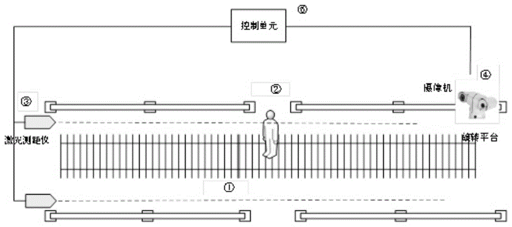
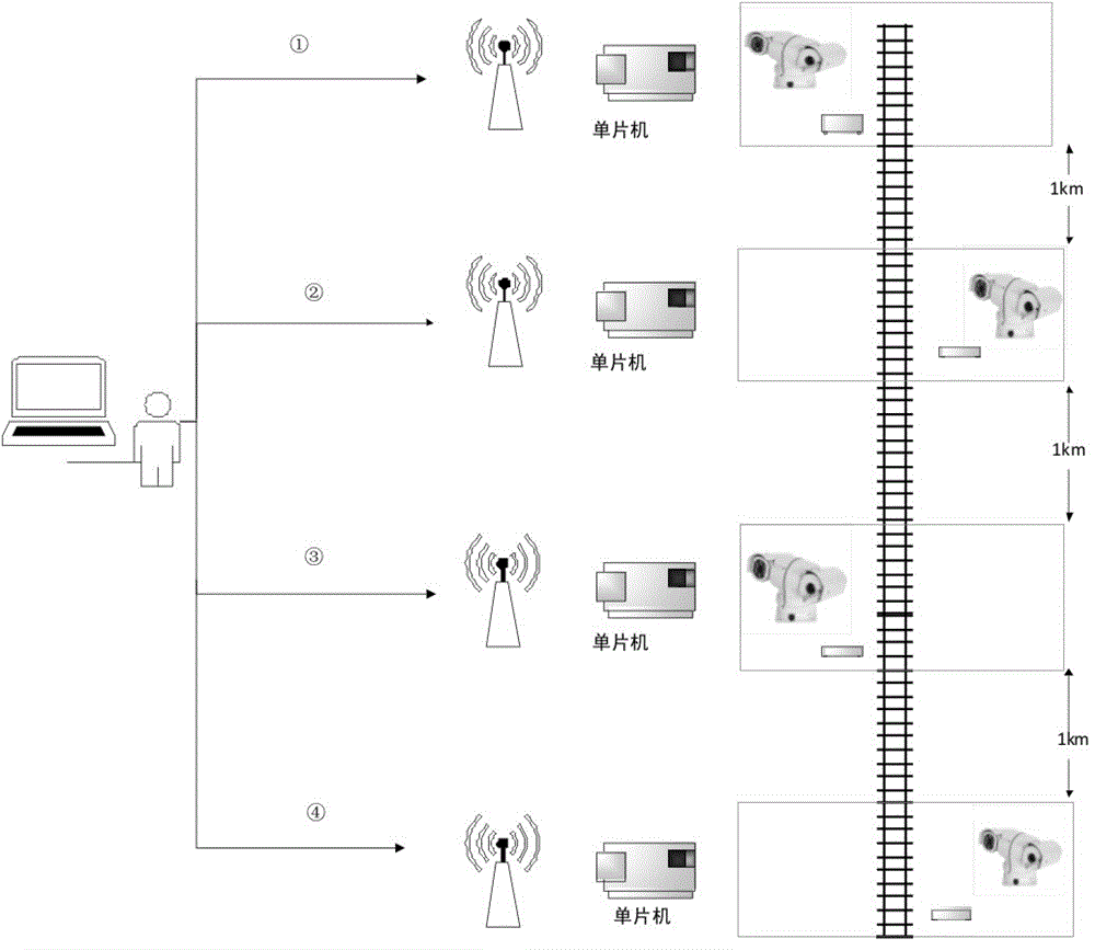
[0024] The present invention is based on laser positioning and high-definition railway safety monitoring system, combining figure 1 and figure 2 , figure 1 It is a schematic diagram of the system structure based on laser positioning and high-definition railway safety monitoring system of the present invention; figure 2 It is an overall railway system diagram based on the laser positioning an...


PUM


Abstract

The invention discloses a high-definition railway line safety monitoring system based on laser positioning. The monitoring system comprises a laser ranger, a control unit, a camera and a rotating platform, wherein the laser ranger, the control unit, the camera and the rotating platform are electrically connected in sequence. The laser ranger is mounted according to the actually required height. The control unit comprises a single chip microcomputer and a video output device. The camera is located on the rotating platform. The monitoring system can judge target pedestrian positions and conduct alarming reminding, and also can obtain pictures of pedestrians so that the pedestrians can be warned or punished afterwards for behaviors.

Description

technical field [0001] The invention belongs to the technical field of railway traffic safety, and in particular relates to a laser-based positioning and high-definition railway safety monitoring system. Background technique [0002] With the development of railway technology, railway monitoring systems are becoming more and more diverse, and the requirements for monitoring systems are getting higher and higher. Most railway monitoring systems are realized by installing monitoring cameras, but there are various defects. The most visible is that the camera has a field of view loophole, and the camera can only monitor the scene in a specific area when the focal length is set, and cannot monitor all railway areas in all directions. [0003] In order to meet the requirements of the monitoring system with higher requirements, ultrasonic distance measurement appeared later. Through the comparison between the obtained distance of pedestrians and the distance of the set reference ta...

Claims


Application Information

Patent Timeline
Patent Type & Authority Applications(China)
IPC IPC(8): B61L23/00G01S17/48H04N7/18
CPCB61L23/007G01S17/48H04N7/18
Inventor 王欣范琳黄贵余黎剑
Owner MIANYANG SKYEYE LASER TECH
Why Eureka
Try Eureka