Supercharge Your Innovation With Domain-Expert AI Agents!

A Method of Using Gradient Arrangement of Cooling Water Nozzles to Control Roll Profile Thermal Crown

A technology of cooling water and control rollers, applied in the direction of profile control, etc., to reduce the possibility of accidents, reduce scrap rate, and improve quality

Active Publication Date: 2016-04-27
BAOSHAN IRON & STEEL CO LTD
View PDF6 Cites 0 Cited by
  • Summary
  • Abstract
  • Description
  • Claims
  • Application Information

AI Technical Summary

Problems solved by technology

[0009] However, the above-mentioned methods all detect and control the camber and do not solve how to eliminate this phenomenon.

Method used


Image

  • A Method of Using Gradient Arrangement of Cooling Water Nozzles to Control Roll Profile Thermal Crown
  • A Method of Using Gradient Arrangement of Cooling Water Nozzles to Control Roll Profile Thermal Crown
  • A Method of Using Gradient Arrangement of Cooling Water Nozzles to Control Roll Profile Thermal Crown

Examples


Embodiment

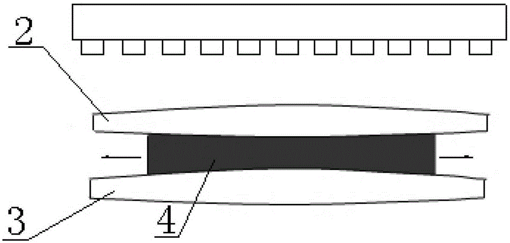
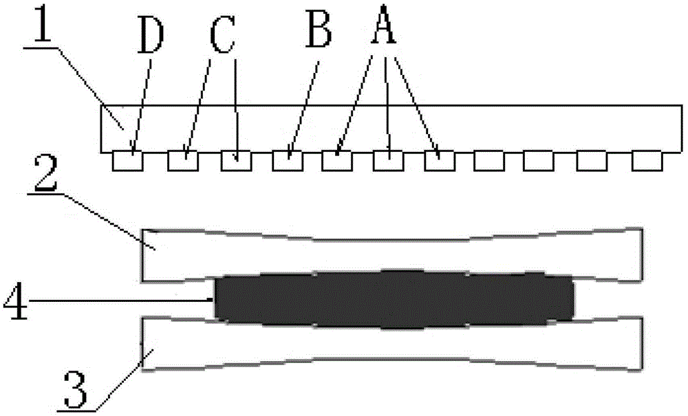
[0030] Such as image 3 As shown, a method for controlling the thermal crown of a roll profile by utilizing the gradient arrangement of cooling water nozzles, the cooling water nozzle group 1 is arranged above the roll 2 on the rolling stand of the rolling mill;

[0031] The cooling water nozzle group is located in the middle position of three main cooling water nozzles A arranged side by side, one auxiliary cooling water nozzle B is respectively arranged on both sides of the main cooling water nozzle, and two auxiliary cooling water nozzles are arranged Two secondary cooling water nozzles C are installed on the side, and finally one terminal cooling water nozzle D is installed at both ends of the entire cooling water nozzle group;

[0032] Redistribute the water spray volume of each water nozzle of the cooling water nozzle group, among which the water spray volume of the main cooling water nozzle A is the largest, the water spray volume of the secondary cooling water nozzle B...


PUM


Abstract

The invention discloses a method of utilizing a cooling water nozzle gradient to control a roll thermal crown. The method comprises the following steps: setting up three main cooling water nozzles side by side in the middle of a cooling water nozzle group, respectively setting up two auxiliary cooling water nozzles on two sides of the main cooling water nozzles, respectively setting up two secondary cooling water nozzles on each of two sides of the auxiliary cooling water nozzles, and at last respectively setting up two ended cooling water nozzles at two ends of the whole cooling water nozzle group, wherein the injection flow of the main cooling water nozzles in the cooling water nozzle group is maximal, the injection flow of the auxiliary cooling water nozzles is secondary, the injection flow of the secondary cooling water nozzles is smaller than that of the auxiliary cooling water nozzles, and the injection flow of the ended cooling water nozzles is minimal. In the invention, the cooling water nozzles are arranged from the center point to the two sides in the roller width direction according to the sequence of larger flow to lower flow in a gradient manner; in the rolling process, along with time, as the rolled strip steel ton is increased, the temperature distortion of the crown in the center of the roller is the largest, the gradient of the thermal crown distribution curve line decreases from the center point to the two sides, the water nozzle flow can be configured correspondingly, and at last the plate off-tracking control purpose can be achieved in the rolling process.

Description

technical field [0001] The present invention relates to an automatic control method for steel rolling in the field of steel production, in particular to a method for controlling the thermal crown variation of the roll profile by gradiently arranging the cooling water nozzles of the rolling mill rolls, so as to realize the plate shape running during the rolling process. partial control. Background technique [0002] At present, in various iron and steel production enterprises, the roughing stand unit usually consists of four rolling mills (hereinafter referred to as R1 rolling mill, R2 rolling mill, R3 rolling mill and R4 rolling mill), among which R2 rolling mill is the most core stand. Normally, the R2 rolling mill adopts 1~5 rolling passes, and in some cases, 1~3 rolling passes are also used. Since the 1~5 pass or the 1~3 pass are reversible pass rolling, the plate shape changes greatly during the rolling process. [0003] With the increasing progress of steel production...

Claims


Application Information

Patent Timeline
Patent Type & Authority Patents(China)
IPC IPC(8): B21B37/32
Inventor 李华明幸利军张先念唐春华周明
Owner BAOSHAN IRON & STEEL CO LTD
Features
  • R&D
  • Intellectual Property
  • Life Sciences
  • Materials
  • Tech Scout
  • Unparalleled Data Quality
  • Higher Quality Content
  • 60% Fewer Hallucinations
Learn More