

Automobile top cover die
A technology for car roofs and moulds, applied in the direction of forming tools, manufacturing tools, metal processing equipment, etc., to achieve the effects of reducing fatigue strength, reducing waste, and improving tea production efficiency
- Summary
- Abstract
- Description
- Claims
- Application Information
AI Technical Summary
Problems solved by technology
Method used
Image

Examples
Embodiment 1
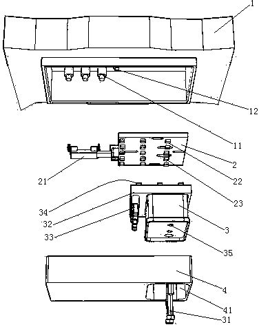
[0026] Embodiment one, see figure 1 , a car roof mold, including an upper mold base 1, a movable push plate 2, a sunroof puncher 3, a suspension bolt 31 and a binder plate 4.
[0027] The upper mold base 1 is provided with a second gas spring 11 extending vertically. There are three second gas springs 11 . The upper mold base 1 is also provided with a positioning protrusion 12 .
[0028] The plane where the movable push plate 2 is located extends along the horizontal direction. The left end of movable push plate 2 is connected with switching cylinder 21. The switching cylinder 21 extends in the left-right direction. The lower surface of the movable push plate 2 is provided with a first jacking projection 22 . The first lifting protrusions 22 have three rows and are distributed along the left and right directions. There are five first jacking bumps in each row of first jacking bumps 22 . The first lifting bump 22 is provided with a strip-shaped via hole 23 extending alon...
Embodiment 2
[0034] Embodiment two, the difference with embodiment one is:
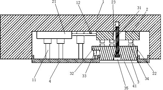
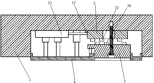
[0035] see Figure 4 , On the upper mold base 1, a push rod 5 is also worn. The push rod 5 can move forward and backward (perpendicular to the paper direction) and left and right. A connecting block 24 is arranged between the movable push plate 2 and the push rod 5 . The connecting block 24 connects the movable push plate 2 and the push rod 5 together.
[0036] The sunroof punch 3 comprises an upper half 36 and a lower half 37 . The upper half 36 and the lower half 37 are overlapped together in the vertical direction.
[0037] see Figure 5 , the first jacking bump 22 and the second jacking bump 34 are elongated structures. The first jacking bump 22 and the second jacking bump 34 are parallel. The extending direction of the first lifting protrusion 22 is perpendicular to the telescoping direction of the switching cylinder.
[0038] The connecting hole 35 is composed of an upper section 351 (the upper secti...
PUM
 Abstract
Description
Claims
Application Information