
High-efficiency rivet riveting device

A high-efficiency technology for pulling rivets, applied in the field of sheet metal processing and manufacturing, can solve the problems of inability to meet mass industrial production and low efficiency, and achieve the effects of high riveting efficiency and increased productivity

Active Publication Date: 2015-11-25
昆山力盟机械工业有限公司
View PDF6 Cites 0 Cited by
  • Summary
  • Abstract
  • Description
  • Claims
  • Application Information

AI Technical Summary

Problems solved by technology

[0004] However, the riveting methods of existing rivets all use a rivet gun, and each person can only pull one rivet at a time per machine.
Low efficiency, unable to meet the needs of mass industrial production

Method used


Image

  • High-efficiency rivet riveting device

Examples


Embodiment Construction

[0019] The present invention is described in further detail now in conjunction with accompanying drawing. These drawings are all simplified schematic diagrams, which only illustrate the basic structure of the present invention in a schematic manner, so they only show the configurations related to the present invention.

[0020] like figure 1 Changes and modifications shown. The technical scope of the present invention is not limited to the content in the specification, but must be determined according to the scope of the claims.

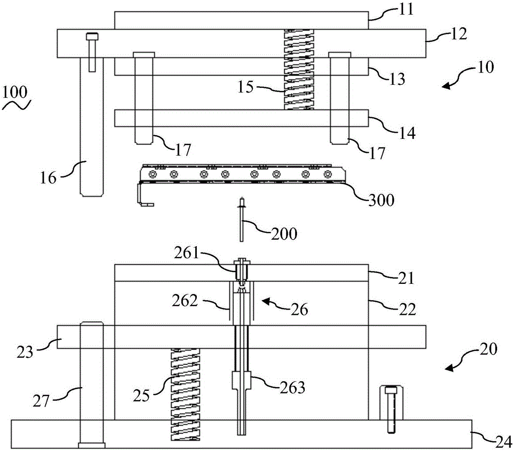
[0021] like figure 1 As shown, the high-efficiency rivet riveting device 100 of the present invention includes: an upper mold mechanism 10, a lower mold mechanism 20, and a driving mechanism. Preferably, the driving mechanism can be a punch press. At this time, the upper die mechanism 10 and the lower die mechanism 20 are arranged on the punch press, and the upper die mechanism 10 can move relative to the lower die mechanism 20 under the drive of ...


PUM


Abstract

The invention relates to an efficient pop-rivet pulling-riveting device which comprises an upper die mechanism, a lower die mechanism and a driving mechanism. The upper die mechanism comprises an upper cover plate, an upper die base, an upper clamping plate, an upper stripping plate, a material pressing elastic piece and a limiting pillar, the upper cover plate, the upper die base and the upper clamping plate are arranged in sequence from top to bottom, the upper stripping plate is arranged below the upper clamping plate, the material pressing elastic piece is arranged between and is connected with the upper cover plate and the upper stripping plate, and the limiting pillar is arranged on and perpendicular to the upper die base. The lower die mechanism comprises a female die plate, a lower base plate, a lower die base, a lower back plate, a reset elastic piece and multiple pulling-riveting assemblies, the female die plate, the lower base plate and the lower die base are arranged in sequence from top to bottom, the lower back plate is arranged below the lower die base, and the reset elastic piece is arranged between the lower die base and the lower back plate. The efficient pop-rivet pulling-riveting device can achieve pulling and riveting of multiple pop-rivets at the same time, riveting efficiency is high, and the yield of production and machining is improved.

Description

technical field [0001] The invention relates to the field of sheet metal processing and manufacturing, in particular to a high-efficiency rivet pulling device. Background technique [0002] The pull rivet is a kind of rivet for single-sided riveting. When it is used, it needs to be riveted with special tools. The above-mentioned special tool is generally a nail puller, and the nail puller is divided into a manual type, an electric type, and a pneumatic type. This type of rivet is especially suitable for riveting occasions where it is inconvenient to use ordinary rivets (riveting from both sides), so it is widely used in construction, automobiles, ships, aircraft, machines, electrical appliances, furniture and other products. [0003] Specifically, when using a rivet for riveting, the rivet is first placed in the firing chamber of the rivet gun, and then aligned with the position to be riveted, the handle of the rivet gun is fired, and the rivet gun will deform the sheet to ...

Claims


Application Information

Patent Timeline
Patent Type & Authority Patents(China)
IPC IPC(8): B21J15/10B21J15/38
Inventor 饶俊杰
Owner 昆山力盟机械工业有限公司
Learn More