Blind hole bearing outer ring detachment puller

A bearing outer ring and pulling tool technology, which is applied in the field of bearing assembly, can solve the problems of difficulty in repairing and disassembling the bearing outer ring, and achieve the effects of easy promotion, simple operation and saving manufacturing cost.

Inactive Publication Date: 2014-08-06
LUOYANG BOPU BEARING MFG
View PDF0 Cites 5 Cited by
  • Summary
  • Abstract
  • Description
  • Claims
  • Application Information

AI Technical Summary

Problems solved by technology

[0003] The purpose of the present invention is to provide a puller for removing the outer ring of a blind hole bearing, which solves the problem that it is difficult to repair and disassemble the outer ring of a blind hole bearing when the clearance is small

Method used


Image

  • Blind hole bearing outer ring detachment puller

Examples


Embodiment Construction

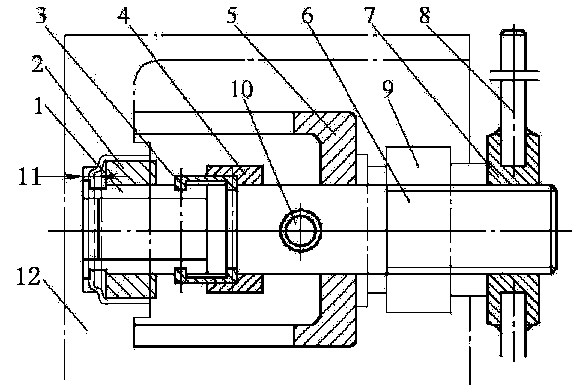
[0010] Below in conjunction with the accompanying drawings, the present invention will be further described; a puller for removing the outer ring of a blind hole bearing, such as figure 1 As shown in , it includes pulling block 1, positioning block 2, coupling block 3, locking ring 4, support frame 5, screw shaft 6, round nut 7, twisting hand 8, release bearing 9 and ejector rod 10; among them, the coupling block 3 is a semicircle, the inner hole of the pull block 1 is in dynamic fit with the outer circle of the front end of the screw shaft 6, the outer circle of the front end of the screw shaft 6 is in dynamic fit with the positioning block 2, and the wrench 8 is fixed on the screw shaft 6 through the round nut 7 , the thread at the rear end of the screw shaft 6 can adopt a fine pitch, so that the round nut 7 can be multi-threaded under the condition of not thickening, a deep hole is drilled in the middle of the screw shaft 6, and the ejector rod 10 is inserted into the screw ...


PUM


Abstract

The invention discloses a blind hole bearing outer ring detachment puller, and belongs to the field of bearing assembly. The puller is characterized in that a pull block (1), a positioning block (2), a connection block (3), a locking ring (4), a supporting frame (5), a screw shaft (6), a round nut (7), a drift holder (8), a release bearing (9) and an ejector rod (10) are included; wherein the connection block (3) are semicircular, an inner hole of the pull block (1) is matched with the outer circle of the front end of the screw shaft (6) in a movable mode, the outer circle of the front end of the screw shaft (6) is in movable fit with the positioning block (2), the drift holder (8) is fixed to the screw shaft (6) through the round nut (7), fine thread pitches are adopted as threads at the rear end of the screw shaft (6), the middle of the screw shaft (6) is provided with a deep hole in a drilled mode, the ejector rod (10) is inserted into the deep hole in the screw shaft (6), and the screw shaft (6) is sleeved with the release bearing (9). The problem that the outer ring of the bearing is difficult to maintain and detach when a gap of a blind hole bearing is small is solved.

Description

technical field [0001] The invention belongs to the field of bearing assembly, in particular to a pulling tool for removing the outer ring of a blind hole bearing. Background technique [0002] In the structural design of some heavy-duty transmissions, the bearings at both ends of the intermediate shaft often use cylindrical roller bearings, and the inner steel mesh of the bearing is directly replaced by the outer circle of the shaft diameter at both ends of the intermediate shaft, so that the outer circle of the shaft diameter at both ends can be made To meet the strength and rigidity requirements of the heavy-duty transmission intermediate shaft; however, things always have their advantages and disadvantages; from the perspective of assembly process, this kind of cylindrical roller bearing assembly, because The cylindrical rolling body is separated from the outer steel mesh, and the outer ring of the bearing is usually pressed into the corresponding hole of the shell first...

Claims


Application Information

Patent Timeline
Patent Type & Authority Applications(China)
IPC IPC(8): B25B27/073
CPCB25B27/06
Inventor 李玉峰白满仓王辉
Owner LUOYANG BOPU BEARING MFG
Why Eureka
Try Eureka