Variable cylinder engine

A technology of engine and cylinder, applied in the field of variable cylinder engine, can solve the problems such as the inability to transfer smoothly, the longer time required for stopping, etc., and achieve the effect of increasing fuel consumption performance and improving fuel consumption performance

Inactive Publication Date: 2014-08-06
MAZDA MOTOR CORP
View PDF7 Cites 7 Cited by
  • Summary
  • Abstract
  • Description
  • Claims
  • Application Information

AI Technical Summary

Problems solved by technology

Therefore, the engine of Patent Document 1 is equipped with a mechanism for stopping the intake valve (valve stop mechanism), but this mechanism is hydraulic, so when the cooling water temperature of the engine is low, the viscosity of the oil for hydraulic control is high, etc. The reason is that the time required to stop the intake valve of the deactivated cylinder (the time required for the operation of the valve stop mechanism) becomes longer, and it cannot be smoothly transferred to the reduced-cylinder operation.

Method used


Image

  • Variable cylinder engine
  • Variable cylinder engine
  • Variable cylinder engine

Examples


Embodiment Construction

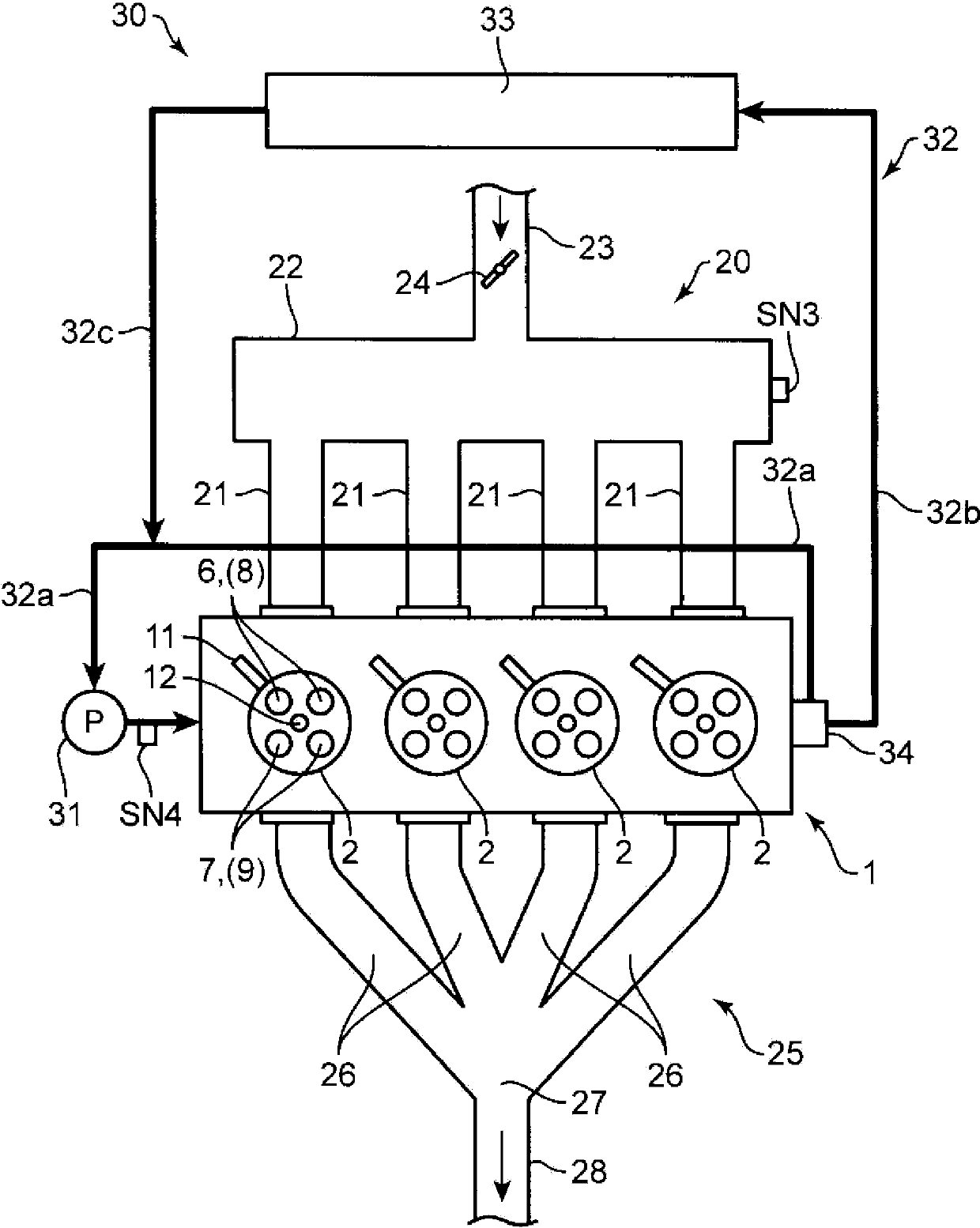
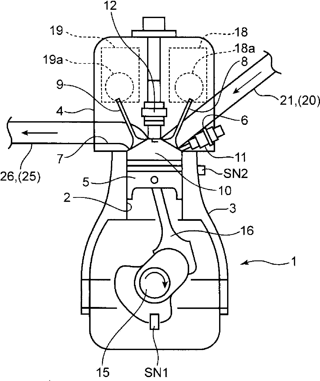
[0040] (1) The overall structure of the engine

[0041] figure 1 and figure 2 It is a figure which shows the structure of the variable cylinder engine which concerns on one Embodiment of this invention. The engine shown in these figures is a four-stroke multi-cylinder gasoline engine mounted on a vehicle as a driving power source. Specifically, the engine is equipped with: an inline four-cylinder engine body 1 having four cylinders 2 arranged in a straight line; an intake passage 20 for introducing air into the engine body 1; The exhaust passage 25 for the exhaust gas generated in the engine; the cooling mechanism 30 for cooling the engine body 1 .

[0042]The engine main body 1 has: a cylinder block 3 in which the four cylinders 2 are formed; a cylinder head 4 provided on the upper portion of the cylinder block 3; and a piston 5 reciprocally slidably inserted into each cylinder 2 .

[0043] A combustion chamber 10 is formed above the piston 5 , and fuel containing gasoli...


PUM


Abstract

A variable cylinder engine is provided. The engine includes an engine body having a plurality of cylinders, a cooling mechanism for cooling the engine body by using a coolant, and a controller for controlling a temperature of the coolant and changing the number of active cylinders according to an operating state of the engine. The controller reduces the number of active cylinders in a reduced-cylinder operating range set within a partial engine load range, and expands the reduced-cylinder operating range to a higher engine load side as the coolant temperature becomes lower.

Description

technical field [0001] The present invention relates to a variable cylinder engine that includes a plurality of cylinders and is capable of performing a reduced-cylinder operation in which some of the plurality of cylinders are stopped. Background technique [0002] As such a variable cylinder engine, for example, the variable cylinder engine of the following patent document 1 is known. Specifically, in this patent document 1, when shifting to the operation with reduced cylinders, control such as stopping the lift operation of the intake valve of the cylinder to be deactivated is executed. Therefore, the engine of Patent Document 1 is equipped with a mechanism for stopping the intake valve (valve stop mechanism), but this mechanism is hydraulic, so when the cooling water temperature of the engine is low, the viscosity of the oil for hydraulic control is high, etc. For this reason, the time required to stop the intake valve of the deactivated cylinder (the time required for ...

Claims


Application Information

Patent Timeline
Patent Type & Authority Applications(China)
IPC IPC(8): F02D17/02
CPCF01P3/20F02D13/08F02D17/02F02D41/0087F02D2200/021Y02T10/12
Inventor 佐佐木润三渡边一丰荒木启二
Owner MAZDA MOTOR CORP
Why Eureka
Try Eureka