

Control device for continuously variable transmission
A technology of continuously variable transmission and control device, which is applied in the direction of transmission, transmission control, and components with teeth, etc. It can solve the problems of noise and vibration level deterioration, and achieve the effect of reducing noise/vibration and suppressing vibration/noise
- Summary
- Abstract
- Description
- Claims
- Application Information
AI Technical Summary
Problems solved by technology
Method used
Image

Examples
no. 1 Embodiment approach
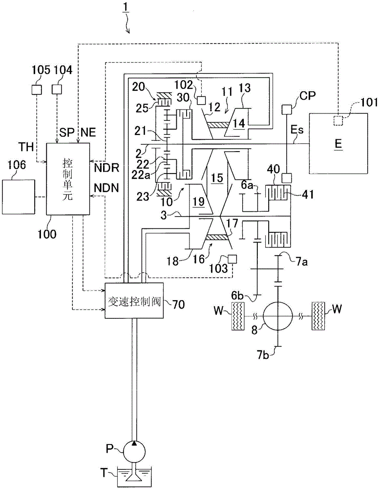
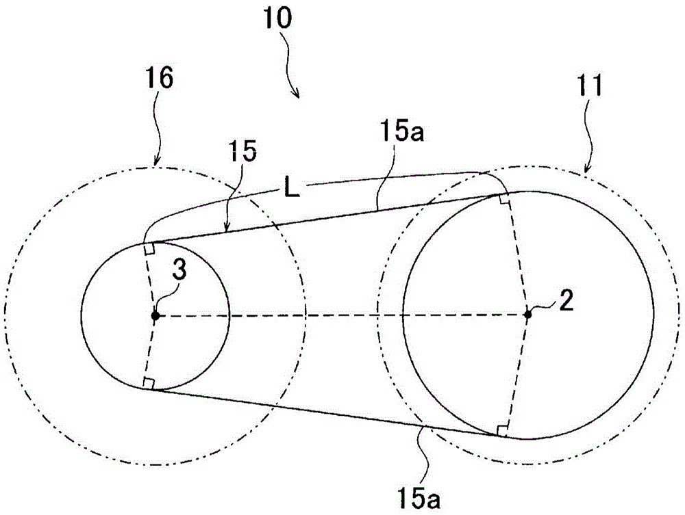
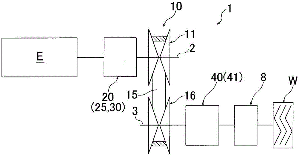
[0044] figure 1 It is a schematic diagram showing a belt-type continuously variable transmission 1 having a control device according to a first embodiment of the present invention. also, figure 2 It is a schematic diagram of the transmission mechanism unit 10 included in the continuously variable transmission 1 . figure 1 The shown continuously variable transmission 1 has: a transmission input shaft (hereinafter referred to as "input shaft") 2 connected to the output shaft Es of the engine E via a coupling mechanism CP; shaft (hereinafter referred to as "subshaft") 3; a transmission mechanism unit 10 arranged between these two shafts 2 and 3; a forward and reverse switching mechanism 20 arranged on the input shaft 2; 3 on the starting clutch mechanism 40; output transmission gear train 6a, 6b, 7a, 7b; and differential mechanism 8.
[0045] The transmission mechanism part 10 is composed of the following components: a driving pulley 11 arranged on the input shaft 2; a driven...
no. 2 Embodiment approach
[0078] Next, a second embodiment of the present invention will be described. In addition, in the description of the second embodiment and the corresponding drawings, the same reference numerals are assigned to the same or corresponding structural parts as those of the first embodiment, and detailed description of these parts will be omitted below. In addition, matters other than those described below are the same as those of the first embodiment. This point is also the same in other embodiments.
[0079] Figure 8 It is a schematic diagram which shows the schematic structure of the continuously variable transmission 1-2 of 2nd Embodiment of this invention. Compared with the continuously variable transmission 1 of the first embodiment, the continuously variable transmission 1 - 2 of the second embodiment omits the starting clutch mechanism (second power transmission part) 40 provided on the same axis as the driven pulley 16 , Instead, only the forward and reverse switching m...
no. 3 Embodiment approach
[0083] Next, a third embodiment of the present invention will be described. Figure 9 It is a figure which shows the schematic structure of the continuously variable transmission 1-3 which concerns on 3rd Embodiment of this invention. Compared with the continuously variable transmission 1 of the first embodiment, the continuously variable transmission 1-3 of the present embodiment omits the power transmission mechanism provided on the same axis as the drive pulley 11, that is, the forward and reverse switching mechanism (first power transmission part). 20, and only has a starting clutch mechanism (second power transmission part) 40 as a power transmission mechanism coaxial with the driven pulley 16. In addition, reference numeral 60 is a damper provided on the input shaft 2 between the engine E and the drive pulley 16 .
[0084] In the case of the continuously variable transmission 1 - 3 of the present embodiment, only the starting clutch mechanism 40 provided on the same sha...
PUM
 Abstract
Description
Claims
Application Information