
Wafer test result map mark modification method

A technology of wafer testing and result graphs, applied in special data processing applications, instruments, electrical digital data processing, etc., can solve problems such as time-consuming, difficult automatic realization, and mistakes

Active Publication Date: 2014-08-06
SHANGHAI HUALI MICROELECTRONICS CORP
View PDF4 Cites 16 Cited by
  • Summary
  • Abstract
  • Description
  • Claims
  • Application Information

AI Technical Summary

Problems solved by technology

[0005] Since the distribution shapes of the unqualified die in the chip function test on the wafer test result map may be various, it is difficult to automatically mark the periphery of the unqualified die in different distribution forms. The traditional method can only Manually complete the labeling in the document of the wafer test result map
[0006] Since there are usually a lot of wafer test result graphs that need to mark bare chips, and hundreds of wafers may be involved in the mass production process, wafer test result graphs need to be processed in this way, so manual processing is very time-consuming and may be lost due to human negligence. mistake

Method used


Image

  • Wafer test result map mark modification method
  • Wafer test result map mark modification method
  • Wafer test result map mark modification method

Examples


Embodiment Construction

[0021] In order to make the content of the present invention clearer and easier to understand, the content of the present invention will be described in detail below in conjunction with specific embodiments and accompanying drawings.

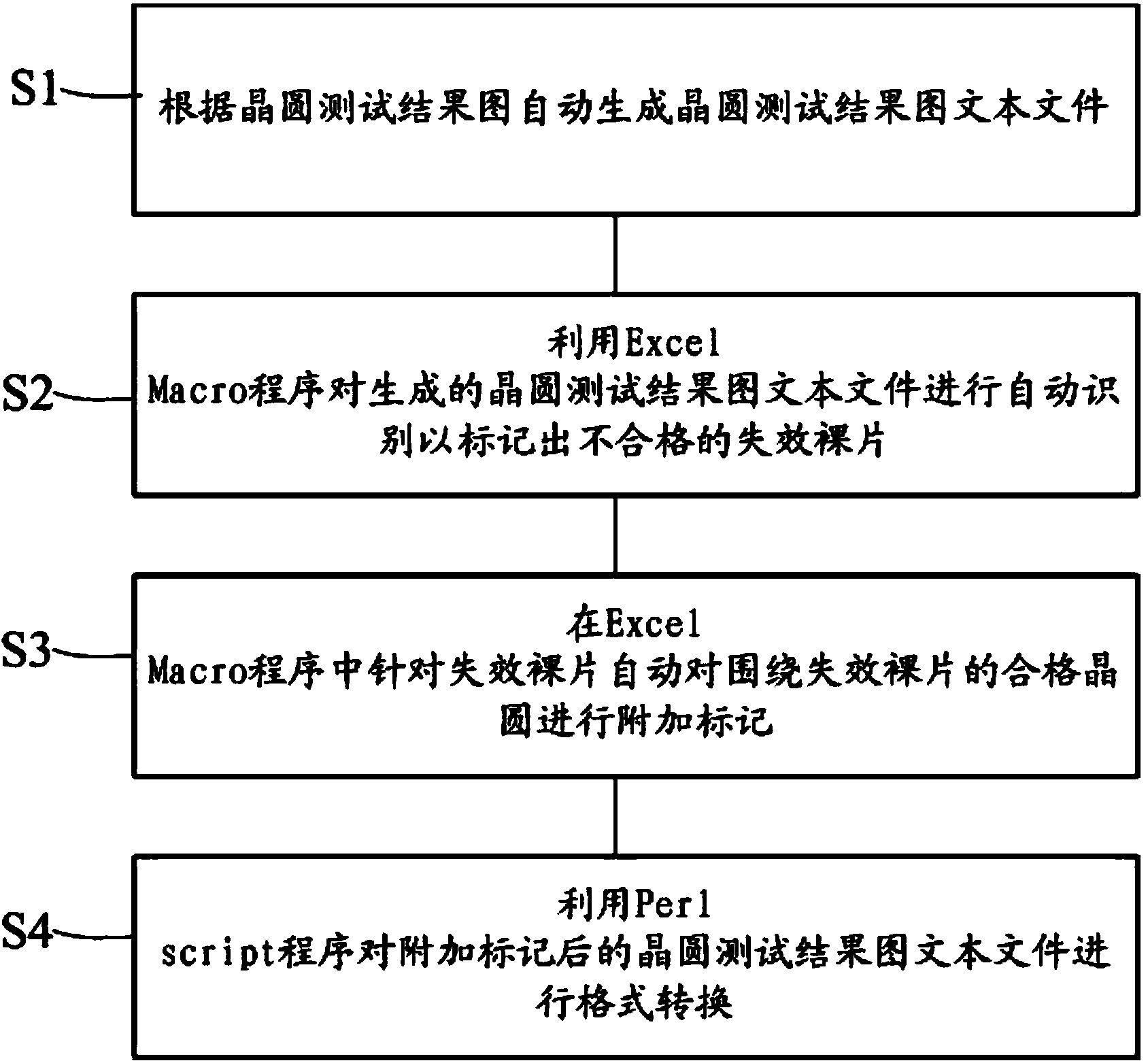
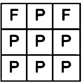
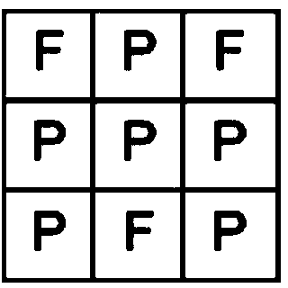
[0022] The present invention adopts the method of program automatic identification, adopts the Jiugongge model, uses Excel Macro to automatically identify the failed dies on the wafer test result diagram, and then automatically replaces them, so that the qualified dies that need to be marked are automatically converted into scrapped The tag of the processed die.

[0023] Among them, the main work of modifying the marking of the wafer test result chart is completed in Excel Macro. For some specific customers who have different format requirements, Perl script can be used to further realize the conversion of other formats. When the whole process is realized, the implementation effect is accurate and fast, and batch processing of a large number of ...


PUM


Abstract

The invention provides a wafer test result map mark modification method. The wafer test result map mark modification method comprises the steps that firstly, a wafer test result map text file is generated automatically according to a wafer test result map; secondly, the generated wafer test result map text file is automatically identified through a program Excel Macro so that unqualified invalid bare chips can be marked; thirdly, additional marking is automatically conducted on qualified wafers surrounding the invalid bare chips according to the invalid bare chips in the program Excel Macro; fourthly, format conversion is conducted on the wafer test result map text file after additional marking through a program Perl script.

Description

technical field [0001] The invention relates to the field of analyzing and improving the yield rate of semiconductor products, and more specifically, the invention relates to a method for modifying the mark of a wafer test result graph. Background technique [0002] Wafer test (CP test, also known as chip functional test) is a wafer-level test. Wafer testing tests the bare die before chip dicing and packaging to test whether the die is qualified. [0003] After the chip function test, a wafer test result map (CP Map: Chip probe Map) representing the distribution of chip function test results will be obtained. In the wafer test result diagram, generally, the qualified dies that pass the chip function test (generally can be marked as Bin1 type) and the unqualified die that fail the chip function test (that is, failed dies) (generally can be marked as Bin class) are marked out respectively. [0004] The wafering customer will select the bare die according to the wafer test r...

Claims


Application Information

Patent Timeline
IPC IPC(8): G06F17/50
Inventor 魏文李强蔡恩静
Owner SHANGHAI HUALI MICROELECTRONICS CORP
Learn More