Gearwheel arrangement

A gear device and gear technology, which is applied in hoisting devices, transmission parts, portable lifting devices, etc., can solve problems such as gear device failure and damage, and achieve the effect of improving jamming and reducing wear

Active Publication Date: 2014-08-13
MIBA SINTER AUSTRIA
View PDF5 Cites 1 Cited by
  • Summary
  • Abstract
  • Description
  • Claims
  • Application Information

AI Technical Summary

Problems solved by technology

As a result this leads to a malfunction of the gear unit and possibly to its destruction

Method used


Image

  • Gearwheel arrangement
  • Gearwheel arrangement
  • Gearwheel arrangement

Examples


Embodiment Construction

[0022] At the outset, it should be pointed out that the same reference symbols or the same component designations are used for the same parts in different embodiments, wherein the disclosure content contained in the entire description can be transferred to the components with the same reference symbols or the same component designations. on the same part. Likewise, selected positions in the description, such as above, below, side, etc., refer to the directly described and illustrated figure and, in the event of a change in position, are sensibly transferred to the new position.

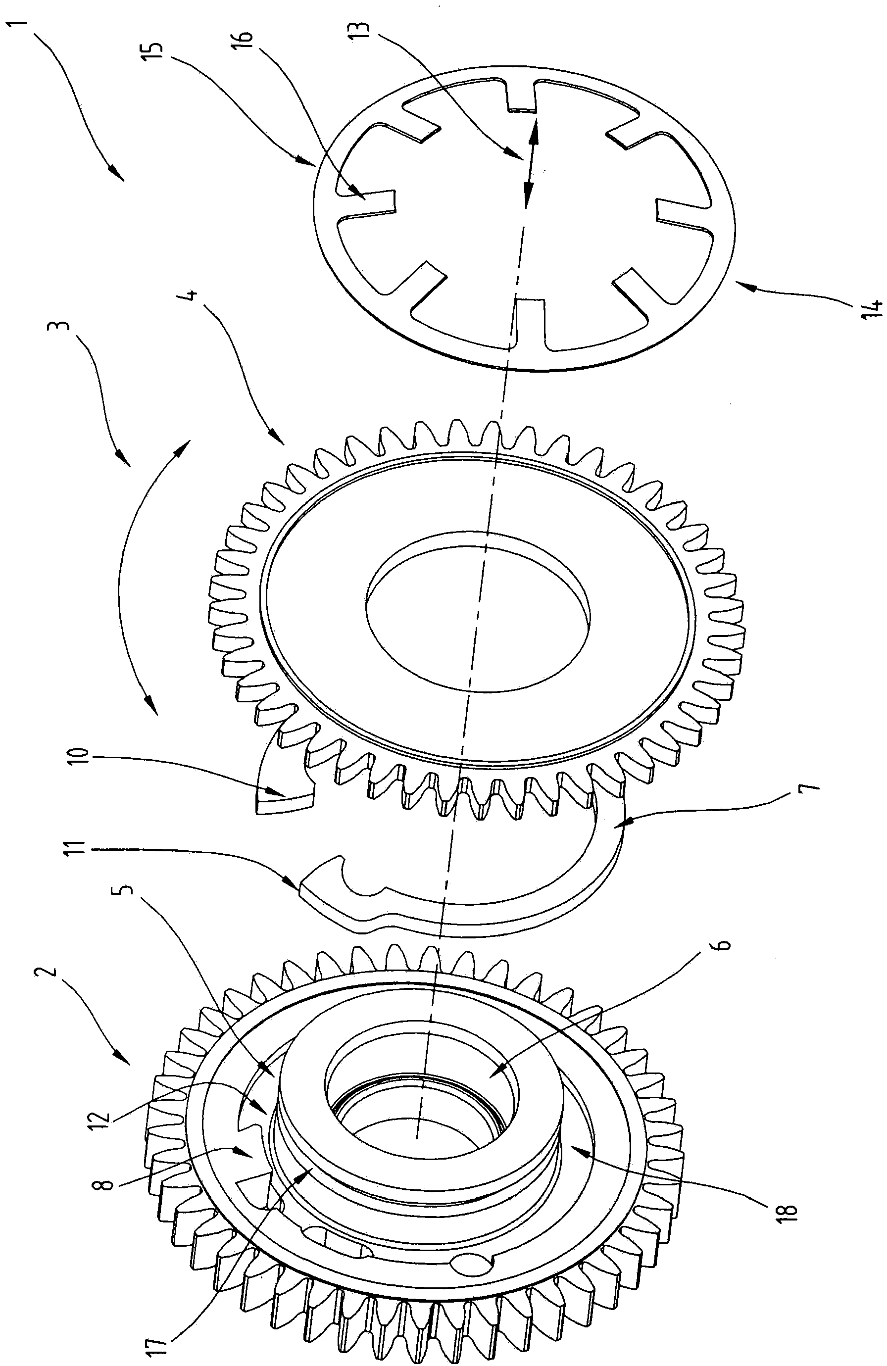
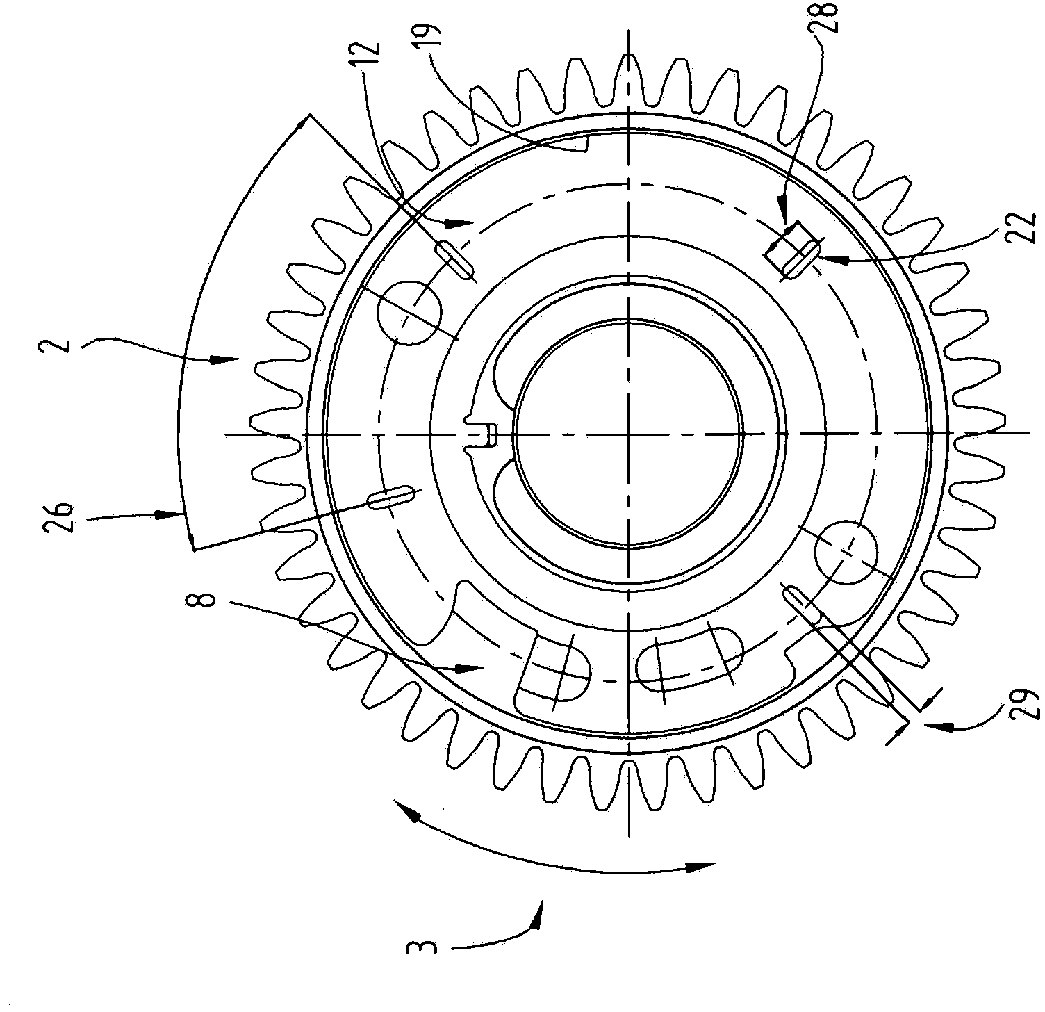
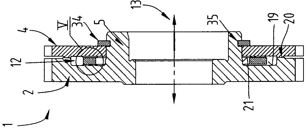
[0023] figure 1 The gear unit 1 is shown in an exploded view, as is known from the prior art. The gearing 1 , also called "split gear", has a main gear 2 and a gear 4 which is relatively rotatable relative to the main gear in the circumferential direction 3 , wherein the main gear 2 has a hub 5 which is in particular connected to the main gear. 2 Constructed in one piece. The rotatable gear 4 is ro...


PUM


Abstract

The invention relates to a gearwheel arrangement (1) with a main gearwheel (2) and a gearwheel (4) rotatable relative to the latter in circumferential direction (3), wherein the main gearwheel (2) comprises a hub (5) on which the rotatable gearwheel (4) is arranged, and with a spring element (7), which is arranged between the main gearwheel (2) and the rotatable gearwheel (4), and by means of which the rotatable gearwheel (4) is pretensioned in circumferential direction (3) against the main gearwheel (2), wherein the main gearwheel (2) comprises at least one first support element (22) and the rotatable gearwheel (4) comprises at least one second support element (23), and wherein the spring element (7) is arranged between the first and the second support element (22, 23) and thereby spaced apart from the first surface (19) of the main gearwheel (2) and from the second surface (21) of the rotatable gearwheel (4).

Description

technical field [0001] The present invention relates to a gear device comprising a main gear and a gear which is relatively rotatable relative to the main gear in the circumferential direction, wherein the main gear has a hub on which the rotatable gear is arranged, and The main gear has a first surface and the rotatable gear has a second surface, and the gear arrangement includes a spring element disposed between the first surface of the main gear and the second surface of the rotatable gear between, and with this spring element, the rotatable gear is pretensioned circumferentially against (gegen) the main gear Background technique [0002] Such a gear unit is known, for example, from WO 2005 / 090830 A1, which gear unit has a gear for a backlash-free spur gear stage, the gear comprises a hub, a gear ring supported by the hub and an annular spring surrounding the hub, the gear ring along the The bisecting plane perpendicular to the axis is divided into two partial rings, nam...

Claims


Application Information

Patent Timeline
Patent Type & Authority Applications(China)
IPC IPC(8): F16H55/17
CPCF16H55/18F16H55/17F16H55/14Y10T74/19916F16H57/0031F16H55/12
Inventor H·布希莱特纳K·迪金格尔C·杜曼斯基
Owner MIBA SINTER AUSTRIA
Why Eureka
Try Eureka