Hip-pot test clamp for motor

A high-voltage, fixture technology, applied in the direction of the casing of the measuring device, can solve the problems of the motor armature not hitting, the existence of detection blind spots, etc., to achieve the effect of quality assurance

Inactive Publication Date: 2014-08-13
WUXI XINHONGTAI ELECTRIC TECH CO LTD
View PDF8 Cites 0 Cited by
  • Summary
  • Abstract
  • Description
  • Claims
  • Application Information

AI Technical Summary

Problems solved by technology

[0002] At present, the HDZ-64-17 series motors are equipped with gearbox components, and the gear on the rotor shaft of the motor is a plastic gear, so the armature and the gearbox of the motor are non-conductive in terms of conductivity. It's just that the high voltage of the electronic parts on the stator and the reducer is hit, the motor armature cannot be hit, and there is a detection blind spot

Method used


Image

  • Hip-pot test clamp for motor

Examples


Embodiment Construction

[0014] The technical solutions of the present invention will be further described below in conjunction with the accompanying drawings and through specific implementation methods.

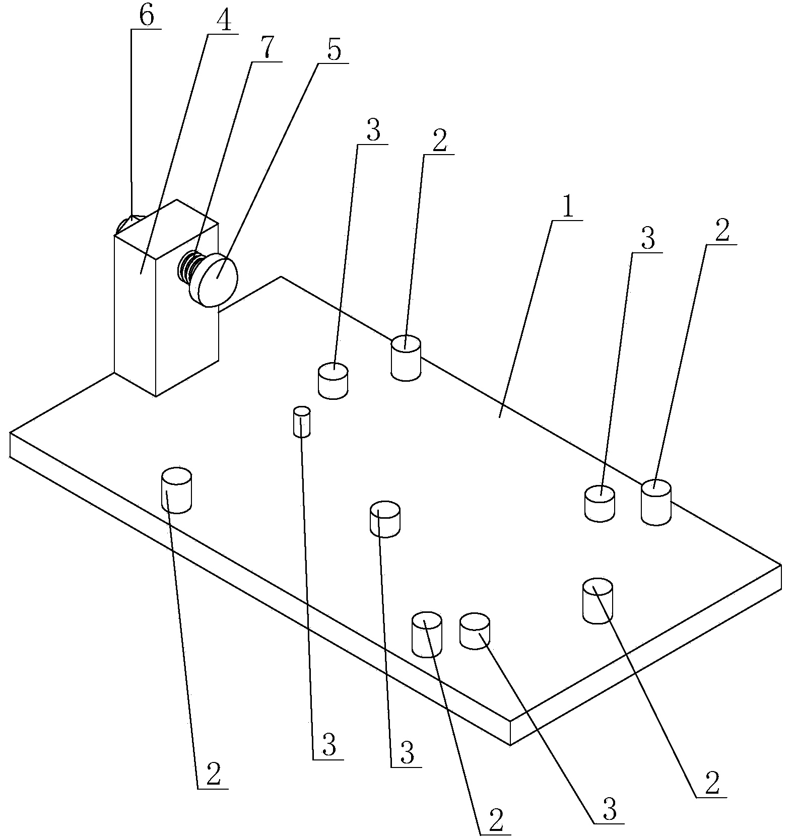
[0015] see figure 1 as shown, figure 1 It is a structural schematic diagram of the electric motor hitting the high-voltage clamp provided in Embodiment 1 of the present invention.

[0016] In this embodiment, a motor high-voltage fixture includes a square bottom plate 1, five positioning pins 2 are arranged on the bottom plate 1 to match the shape and size of the motor, and the five positioning pins 2 enclose a space for placing the motor. area, and five support pins 3 for supporting the motor bottom plate are arranged in the area surrounded by the five positioning pins, the height of the five support pins 3 is the same, and one side of the bottom plate 1 is vertically provided with Support plate 4, the support plate 4 is provided with a tightening device for tightening the motor stator when the h...


PUM


Abstract

The invention discloses a hip-pot test clamp for a motor. The hip-pot test clamp comprises a bottom plate, wherein a plurality of positioning pins matched with the motor in shape and size are arranged on the bottom plate, a plurality of supporting pins for supporting the bottom plate of the motor are arranged in an area defined by the plurality of positioning pins, a supporting plate is arranged on one side of the bottom plate and provided with a pressing device which is used for pressing against a stator of the motor when a hip-pot test is carried out, and the bottom plate, the supporting plate, the positioning pins, the supporting pins and a pressing device are all made of conductive metal materials. According to the hip-pot test clamp for the motor, the hip-pot test on electronic parts on the stator, a rotor and a speed reduction mechanism can be realized, non-detection zones do not exit, the quality of products can be guaranteed, and the motor is convenient and fast to assemble and disassemble through the clamp.

Description

technical field [0001] The invention relates to a clamp, in particular to a high-voltage clamp driven by a motor. Background technique [0002] At present, the HDZ-64-17 series motors are equipped with gearbox components, and the gear on the rotor shaft of the motor is a plastic gear, so the armature and the gearbox of the motor are non-conductive in terms of conductivity. It's just that the high voltage of the electronic parts on the stator and the reduction box is hit, the motor armature cannot be hit, and there is a detection blind spot. Contents of the invention [0003] The purpose of the present invention is to provide a motor high voltage clamp, which can simultaneously carry out high voltage on the stator, rotor, and electronic components on the reduction mechanism, so as to solve the above-mentioned problems in the prior art of motor high voltage. [0004] For reaching this purpose, the present invention adopts following technical scheme: [0005] A motor high-v...

Claims


Application Information

Patent Timeline
Patent Type & Authority Applications(China)
IPC IPC(8): G01R1/04
Inventor 邱伟峰赵敏海杨智勇
Owner WUXI XINHONGTAI ELECTRIC TECH CO LTD
Why Eureka
Try Eureka