Peak current regulating system and method used in source transformation system

A power conversion, primary current technology, applied in the direction of converting DC power input to DC power output, adjusting electrical variables, control/regulating systems, etc., can solve the problem that the output load of the power conversion system cannot provide an effective response.

Active Publication Date: 2014-08-13
ON BRIGHT ELECTRONICS SHANGHAI
View PDF4 Cites 33 Cited by
  • Summary
  • Abstract
  • Description
  • Claims
  • Application Information

AI Technical Summary

Problems solved by technology

[0015] However, the power conversion system 100 often cannot

Method used


Image

  • Peak current regulating system and method used in source transformation system
  • Peak current regulating system and method used in source transformation system
  • Peak current regulating system and method used in source transformation system

Examples


Embodiment Construction

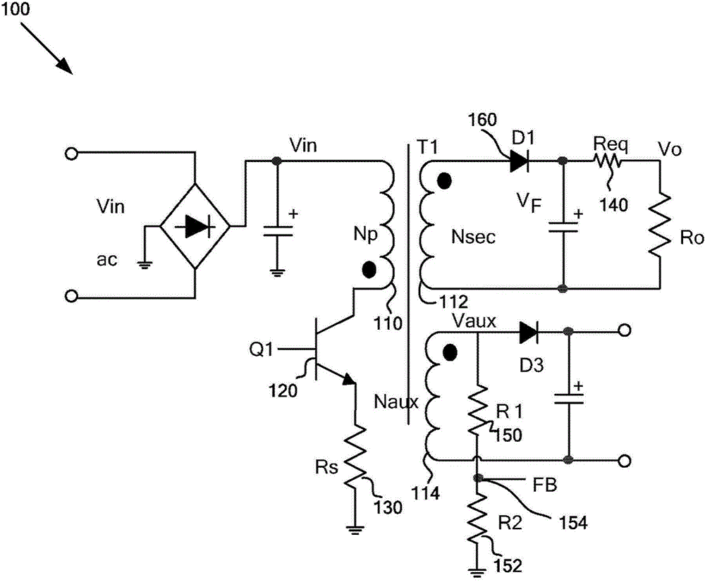
[0035] The present invention relates to integrated circuits. More specifically, the present invention provides regulation of peak current. Merely by way of example, the invention has been applied to power conversion systems. It will be appreciated, however, that the invention has a much broader range of applicability.

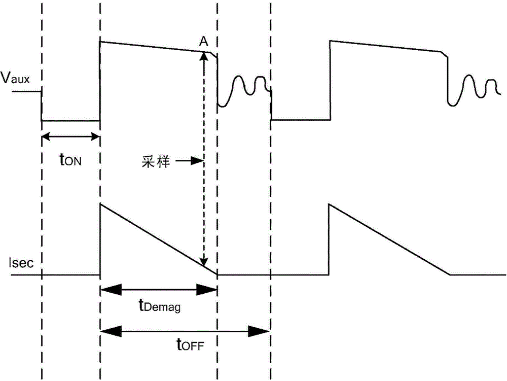
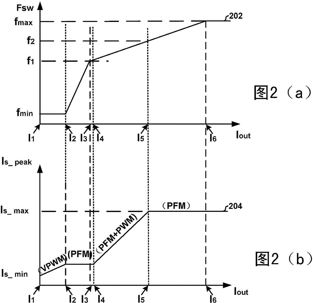
[0036] Referring to FIG. 1( a ) and FIG. 1( b ), information about the output voltage of the power conversion system 100 is often only sampled once per switching cycle. The switching period is inversely proportional to the switching frequency, and the switching frequency is often set lower under no-load or light-load conditions to reduce power dissipation. However, for the power conversion system 100, a low switching frequency generally results in poor dynamic response if the load changes from no load or light load to full load. For example, if the switching frequency is several hundred Hz under no-load or light-load conditions, information on the output vol...


PUM


Abstract

The invention discloses a peak current regulating system and method used in a source transformation system. The system and method are used for regulating the output of the source transformation system. A system controller comprises a signal generator and a modulating and driving component, wherein the signal generator is used for at least receiving a first signal and a second signal and generating a third signal, the first signal indicates the input voltage received by a primary winding of the source transformation system, the second signal indicates the primary current passing through the primary winding, and the modulating and driving component is used for at least receiving the third signal, generating a driving signal based on the information relevant to the third signal, and outputting the driving signal to a switch to affect the primary current.

Description

[0001] Instructions for Divisional Application [0002] This application is a divisional application of a Chinese invention patent application with the filing date of December 10, 2012, the application number of 201210529679.4, and the title of "System and Method for Peak Current Regulation in Power Conversion Systems". technical field [0003] The present invention relates to integrated circuits. More specifically, the present invention provides regulation of peak current. Merely by way of example, the invention has been applied to power conversion systems. It will be appreciated, however, that the invention has a much broader range of applicability. Background technique [0004] Generally, conventional power conversion systems often use a transformer to isolate the input voltage on the primary side and the output voltage on the secondary side. To regulate the output voltage, certain components such as TL431 and optocoupler can be used to send a feedback signal from the...

Claims


Application Information

Patent Timeline
IPC IPC(8): H02M3/335
Inventor 林元王伟华张秀红方烈义
Owner ON BRIGHT ELECTRONICS SHANGHAI
Why Eureka
Try Eureka