
Ball guide bushing and guide column with sliding ways

A technology of balls and guide bushes, which is applied in metal processing equipment, forming tools, manufacturing tools, etc., and can solve problems such as the shaking of the ball cage, guide bushes and guide posts in the horizontal direction

Inactive Publication Date: 2014-08-20
SUZHOU GUANGSHUO PRECISION ELECTRONICS
View PDF5 Cites 5 Cited by
  • Summary
  • Abstract
  • Description
  • Claims
  • Application Information

AI Technical Summary

Problems solved by technology

In the stamping die, the mold guide pillars usually used are made of steel, and the gap between the guide bush and the guide pillar is adopted. The ball retainer with a large number of balls is usually used between the guide pillar and the guide bush. , but long-term use will cause excess clearance between the ball cage and the guide sleeve and guide post, which will cause it to shake in the horizontal direction. In order to avoid its horizontal shake, the relative distance between the guide sleeve and the guide post should be reduced Rotation, but also to avoid the relative movement between the guide bush and the guide column and the ball cage

Method used


Image

  • Ball guide bushing and guide column with sliding ways
  • Ball guide bushing and guide column with sliding ways
  • Ball guide bushing and guide column with sliding ways

Examples


Embodiment Construction

[0018] The present invention will now be further described in detail in conjunction with the accompanying drawings and embodiments. These drawings are all simplified schematic diagrams, only illustrating the basic structure of the present invention in a schematic manner, so it only shows the composition related to the present invention.

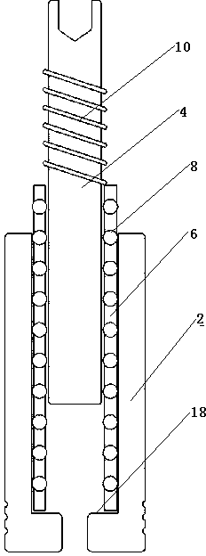
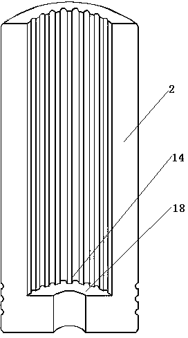
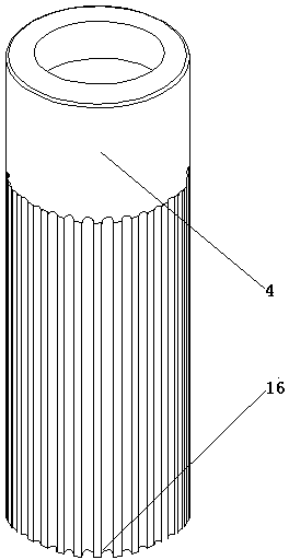
[0019] Such as figure 1 , figure 2 , image 3 and Figure 4 As shown, a ball guide bush guide column with a slideway includes an outer guide sleeve 2, a ball cage 6 sleeved on the inner layer of the guide sleeve 2, a guide column 4 sleeved inside the ball cage 6, and balls The retainer 6 is provided with several rows and columns of retaining holes 12, the arrangement direction of each retaining hole 12 is parallel to the axial direction of the ball retainer 6, each retaining hole 12 is nested with a ball 8, and the inner wall of the guide sleeve 2 is provided with a Keep the inner slideway 14 with the same number of rows in the holes 12, ...


PUM


Abstract

The invention relates to a ball guide bushing and guide column with sliding ways. The ball guide bushing and guide column comprises a guide bushing body, a ball holder arranged in the guide bushing body in a sleeved mode and a guide column body arranged in the ball holder in a sleeved mode. A plurality of longitudinal lines of holding holes are formed in the ball holder, balls are embedded in the holding holes, a plurality of concave inner sliding ways identical with the guide bushing body in the axial direction are arranged on the inner wall of the guide bushing body, a plurality of concave outer sliding ways identical with the guide column body in the axial direction are arranged on the outer wall of the guide column body, the number of the inner sliding ways and the number of the outer sliding ways are equal to the number of the longitudinal lines of the holding holes, and the balls are clamped in the inner sliding ways and the outer sliding ways at the same time. The axial arc-shaped sliding ways are formed on the inner wall of the guide bushing body and the outer wall of the guide column body, the balls are clamped by the holding holes and can be clamped by the sliding ways on the guide bushing body and the guide column body in a matched mode, the balls can only axially roll along the guide column body and the guide bushing body, relative rotation among the guide column body, the ball holder and the guide bushing body is avoided, the relative shake between the guide column body and the guide bushing body is smaller, the motion position is more accurate, and then machining accuracy is improved.

Description

technical field [0001] The invention relates to a novel guide bush and guide post for a continuous grinding tool, in particular to a guide post for a ball guide bush with a slideway. Background technique [0002] In the stamping die in the prior art, guide sleeves and guide posts are arranged between the upper and lower seats of the die, so that the die can be positioned and guided when it moves up and down, so that the stamping and forming work can be performed accurately. In the stamping die, the mold guide pillars usually used are made of steel, and the gap between the guide bush and the guide pillar is adopted. The ball retainer with a large number of balls is usually used between the guide pillar and the guide bush. , but long-term use will cause excess clearance between the ball cage and the guide sleeve and guide post, which will cause it to shake in the horizontal direction. In order to avoid its horizontal shake, the relative distance between the guide sleeve an...

Claims


Application Information

Patent Timeline
IPC IPC(8): B21D37/12
Inventor 朱磊
Owner SUZHOU GUANGSHUO PRECISION ELECTRONICS
Learn More