A pneumatic impact wrench auxiliary device
What is Al technical title?
Al technical title is built by PatSnap Al team. It summarizes the technical point description of the patent document.
An auxiliary device and impact wrench technology, which is applied in the direction of wrench, wrench, screwdriver, etc., can solve the problems of large human body injury, uneven locking force, and loose nut lock, so as to reduce labor intensity, ensure driving safety, and use Safe and reliable effect
Active Publication Date: 2015-11-11
SHANTOU TONGLI MACHINERY MFG
View PDF6 Cites 0 Cited by
Summary
Abstract
Description
Claims
Application Information
AI Technical Summary
This helps you quickly interpret patents by identifying the three key elements:
Problems solved by technology
Method used
Benefits of technology
Problems solved by technology
Because the pneumatic impact wrench is heavy and vibrates very badly during disassembly and assembly, the disassembly and assembly work efficiency of the portable pneumatic impact wrench is low, the work is extremely difficult and uncomfortable, and the damage to the human body is relatively large.
[0004] In addition, because the portable pneumatic impact wrench is easy to make people tired, it is easy to lock the nut tightly or the locking force is uneven.
In this way, the nuts are prone to loosen during the running of the wheel, which leads to accidents.
Method used
Image
Click on the blue label to locate the original text in one second.
Reading with bidirectional positioning of images and text.
Examples
Embodiment Construction
[0021] Further description will be given below in conjunction with the accompanying drawings and preferred embodiments of the present invention.
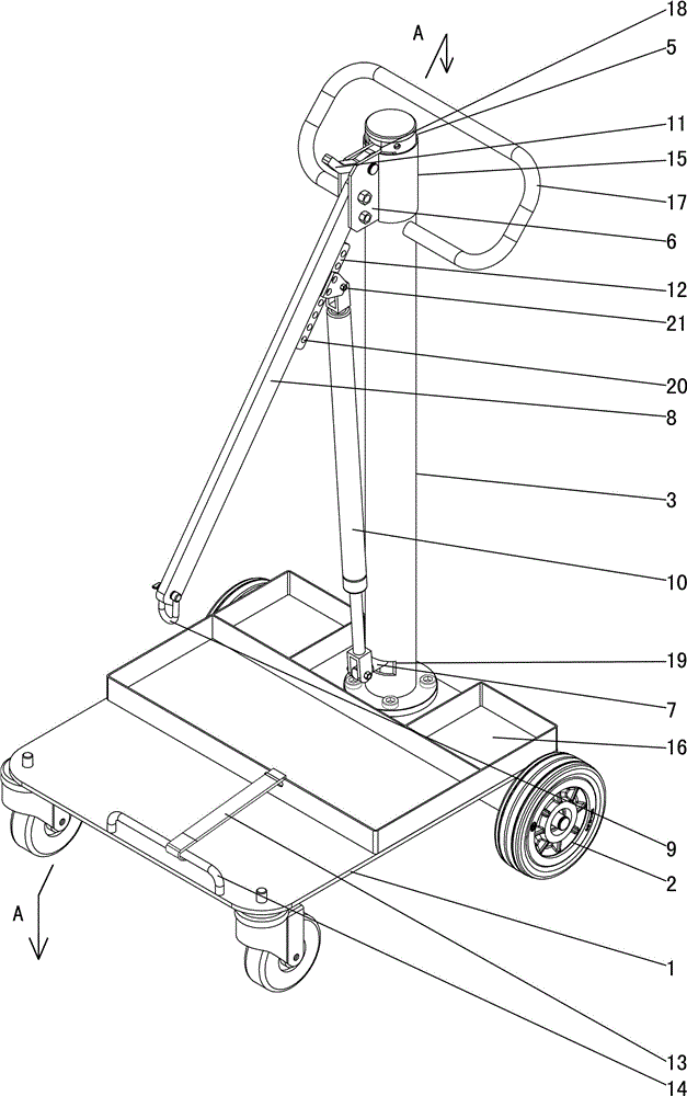
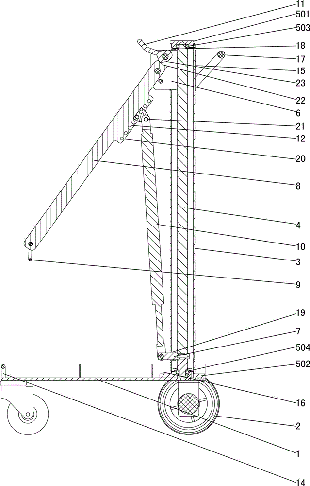
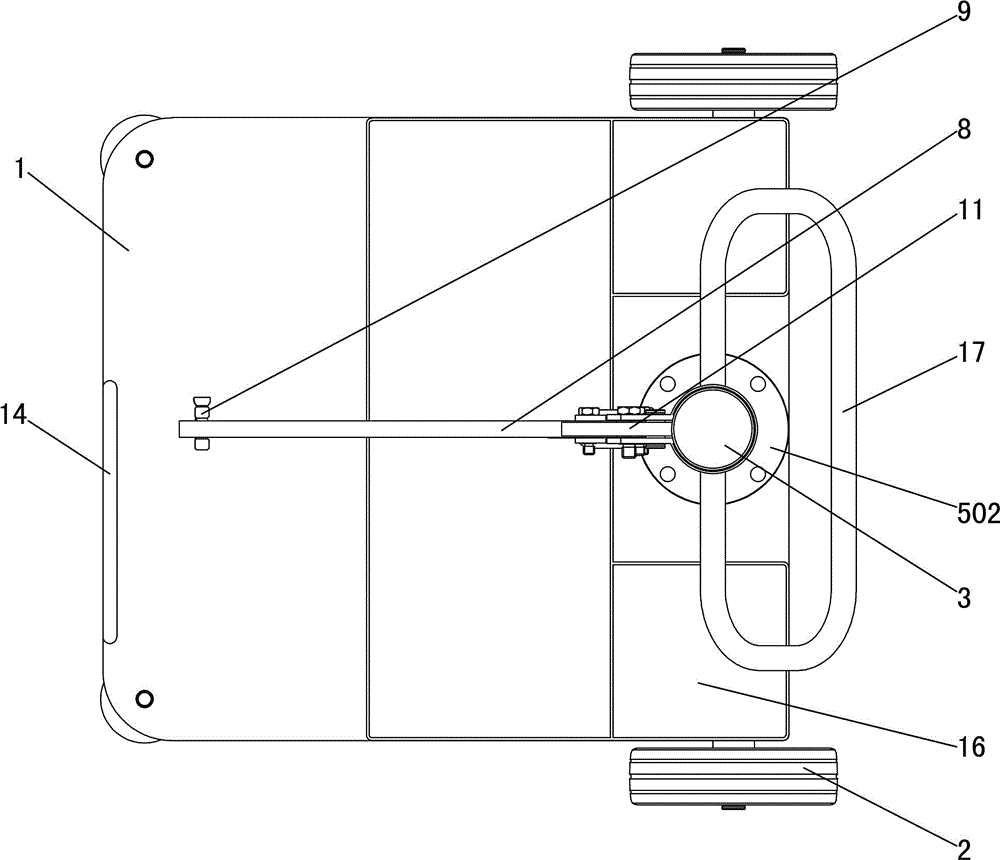
[0022] Such as figure 1 , figure 2 and image 3 As shown, this pneumatic impact wrench auxiliary device includes chassis 1, wheels 2, cylindrical column 3, rotating shaft 4, bearing assembly 5, upper limit block 6, lower limit block 7, boom 8, suspension ring 9, load telescopic rod 10. Lock handle 11, torque adjustment block 12, tightening rope 13, U-shaped iron 14, shield 15, tool tray 16 and handle 17; wheels 2 are installed under the chassis 1, and the tool tray and U-shaped iron are installed on On the chassis, one end of the binding rope is fixed on the U-shaped iron; the cylindrical column 3 is installed vertically on the chassis 1; the handle 17 is installed on the upper end of the cylindrical column 3; In the column 3; the upper end of the cylindrical column 3 is provided with an upper limit port 18, and the lower end of...
PUM
Abstract
The invention relates to an auxiliary device of a pneumatic impact wrench. The auxiliary device comprises a base plate, wheels, a cylindrical stand column, a rotating shaft, a bearing assembly, an upper limiting block, a lower limiting block, a suspension arm, a suspension ring and a load stretchable rod. The cylindrical stand column is vertically installed on the base plate, the rotating shaft is installed in the cylindrical stand column in a rotatable mode through the bearing assembly, an upper limiting opening is formed in the upper end of the cylindrical stand column, a lower limiting opening is formed in the lower end of the cylindrical stand column, the upper limiting block is connected with the upper end of the rotating shaft and extends out from the upper limiting opening, the lower limiting block is connected with the lower end of the rotating shaft and extends out from the lower limiting opening, the upper end of the suspension arm is hinged to the upper limiting block, the suspension ring is installed at the lower end of the suspension arm, the lower end of the load stretchable rod is hinged to the lower limiting block, and the upper end of the load stretchable rod is hinged to the middle of the suspension arm. The suspension ring at the lower end of the suspension arm can freely move in the horizontal direction and the vertical direction, when a nut is disassembled and assembled, labor is greatly saved, the auxiliary device is convenient to use, the labor intensity is greatly reduced, fatigue can be avoided, the locking degree is guaranteed, and the traffic safety is further guaranteed.
Description
technical field [0001] The invention relates to a tire removal tool, in particular to an auxiliary device for a pneumatic impact wrench. Background technique [0002] When repairing car wheels, the tires must be removed from the car, and the removal and installation of wheel nuts saves time and effort, which is a headache. [0003] At present, the following method is used to disassemble the nuts on the wheels: that is, to disassemble the wheel nuts directly with a special wheel dismounting pneumatic impact wrench manually carried by manpower. Because the pneumatic impact wrench is cumbersome and vibrates very badly during disassembly and assembly, the disassembly and assembly work efficiency of the portable pneumatic impact wrench is low, the work is extremely difficult and uncomfortable, and the damage to the human body is relatively large. [0004] In addition, because the portable pneumatic impact wrench is easy to make people tired, it is easy to lock the nut tightly or...
Claims
Application Information
Patent Timeline
Application Date:The date an application was filed.
Publication Date:The date a patent or application was officially published.
First Publication Date:The earliest publication date of a patent with the same application number.
Issue Date:Publication date of the patent grant document.
PCT Entry Date:The Entry date of PCT National Phase.
Estimated Expiry Date:The statutory expiry date of a patent right according to the Patent Law, and it is the longest term of protection that the patent right can achieve without the termination of the patent right due to other reasons(Term extension factor has been taken into account ).
Invalid Date:Actual expiry date is based on effective date or publication date of legal transaction data of invalid patent.