
An automatic connection and locking device for large-scale barrel section equipment

An automatic connection and locking device technology, which is applied in the direction of connecting components, mechanical equipment, friction clamping detachable fasteners, etc., can solve the problems of machine weight and size restrictions, unfavorable barrel section installation, and large space occupation , to achieve the effect of convenient maintenance and repair, small space occupation and short time required

Active Publication Date: 2020-11-06
YANSHAN UNIV
View PDF7 Cites 0 Cited by
  • Summary
  • Abstract
  • Description
  • Claims
  • Application Information

AI Technical Summary

Problems solved by technology

[0004] Restricted by the environment and working conditions of use, there are restrictions on the weight and size of the machine used. However, there are fewer types of automatic connecting devices for barrel sections, and the structures are complex and occupy a large space, which is not conducive to the transportation and operation of barrel sections. Installation of other equipment on the cylinder

Method used


Image

  • An automatic connection and locking device for large-scale barrel section equipment
  • An automatic connection and locking device for large-scale barrel section equipment
  • An automatic connection and locking device for large-scale barrel section equipment

Examples


Embodiment Construction

[0038] The following will clearly and completely describe the technical solutions in the embodiments of the present invention with reference to the accompanying drawings in the embodiments of the present invention. Obviously, the described embodiments are only some, not all, embodiments of the present invention. Based on the embodiments of the present invention, all other embodiments obtained by persons of ordinary skill in the art without making creative efforts belong to the protection scope of the present invention.

[0039] The purpose of the present invention is to provide an automatic connection and locking device for large-scale barrel section equipment, which can replace the traditional bolt connection, realize fast connection and locking between the upper and lower barrels, and is easy to operate and automatic.

[0040] In order to make the above objects, features and advantages of the present invention more comprehensible, the present invention will be further describ...


PUM


Abstract

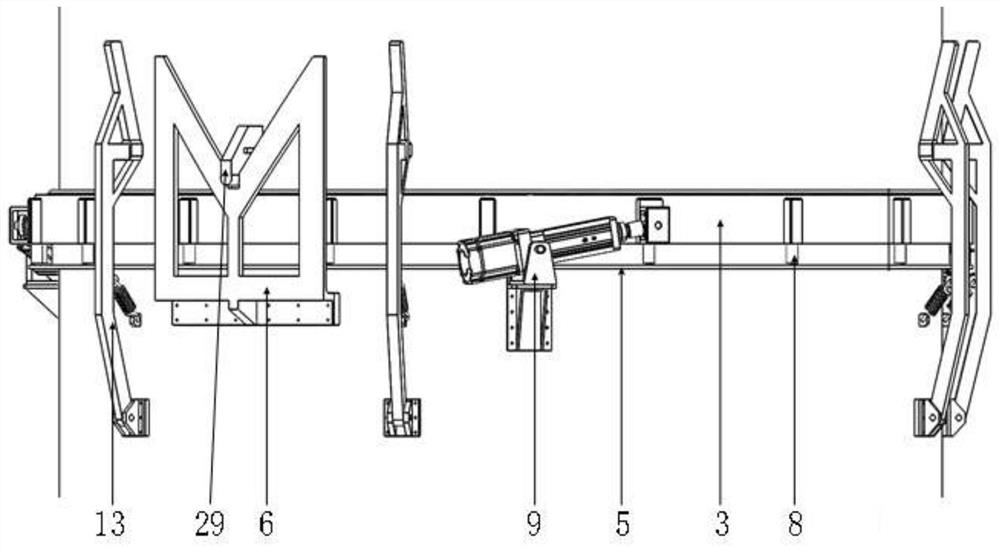
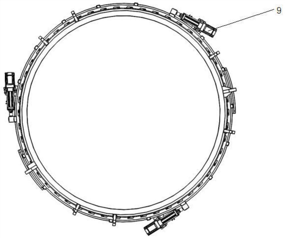
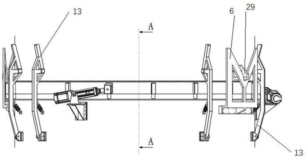
The invention discloses a large cylinder segment device automatic connection locking device. The large cylinder segment device automatic connection locking device comprises an upper cylinder, a lowercylinder, a locking ring, a limiting clamp ring, a support plate, two quadrant plates, centering mechanisms, a spring roller mechanism and drive mechanisms, wherein the upper cylinder is butted with the lower cylinder, the limiting clamp ring is installed in a groove in the outer side of a connection end of the lower cylinder, the locking ring is installed on the outer side of the connection end of the lower cylinder, the support plate is installed on the lower cylinder and located on the lower portion of the locking ring, the spring roller mechanism is installed in a boss on the outer side ofthe locking ring, a rolling ball at the lower end of the spring roller mechanism makes contact with the support plate, the two quadrant plates are symmetrically installed on the outer side of the lower cylinder, the two centering mechanisms are pairwise installed on the outer side of the lower cylinder in a non-uniform distribution mode, three sets of the drive mechanisms are arranged, and uniformly distributed on the outer side of the lower cylinder, one end of an electric cylinder is connected with the lower cylinder through a connection frame, the other end of the electric cylinder is connected with the locking ring through a head part connection block, and when the electric cylinder stretches out and draws back, the locking ring is driven to rotate, and completes connection locking orunlocking separation of the upper cylinder and the lower cylinder.

Description

technical field [0001] The invention relates to the technical field of connection and locking of barrel section equipment, in particular to an automatic connection and locking device for large barrel section equipment. Background technique [0002] With the development of machinery, mechanical devices are becoming more and more diverse, and their structures are becoming more and more sophisticated, and it is becoming more and more common to use mechanical devices to solve problems in life. Mechanical devices can help people do some work, save manpower, and can also replace people to complete many jobs that cannot be done by humans. [0003] The existing barrel section connection method is still the traditional bolt connection, and manual operation is required for installation and disassembly, which is time-consuming and labor-intensive. Therefore, there is a need for a device that can automatically connect and lock the barrel sections, and the structure of the device is as ...

Claims


Application Information

Patent Timeline
Patent Type & Authority Patents(China)
IPC IPC(8): F16B2/06
CPCF16B2/06
Inventor 曾达幸庞有金杜习春田克俭宋彦佐齐乔林苏雷杨卫杰任相名
Owner YANSHAN UNIV
Learn More