Lever type handle and lock assembly for the same

a technology of lever type handle and lock assembly, which is applied in the direction of wing knobs, mechanical control devices, keyhole guards, etc., can solve the problems of inconvenient change of structure with the key to the structure, inability to have uniform appearance of handles, and poor etc., to achieve simplified lock assembly structure, easy operation by users, and excellent appearance of lever type handles

Active Publication Date: 2015-04-14
KOH YOUNGKYUN
View PDF12 Cites 4 Cited by
  • Summary
  • Abstract
  • Description
  • Claims
  • Application Information

AI Technical Summary

Benefits of technology

[0023]According to an embodiment of the invention, a key module is positioned inside a handle portion, and thus, an additional hole for installing the key module is not formed in a window or a door. Since the key module is not exposed to the outside and is not shown from the front of the door, the appearance of a lever type handle is excellent. Also, the key module is positioned at an end portion of the handle portion, and therefore, the key module can be easily operated by a user through using a key member.
[0024]Further, a structure of the lock assembly is simplified to the key module, a rotation transmitter, and a rotary shaft. Accordingly, a number of components can be reduced, and the manufacturing cost can be decreased. In addition, it is convenient to assemble and disassemble the lock assembly.
[0025]Furthermore, by unifying shapes of the key modules, a key module having a key way, a key module having a groove for a coin, or a key module having a grip portion can be freely selected. Also, when the key module is not necessary, a finishing module can be used instead of the key module. That is, the key module and / or the finishing module can be variously applied according to user's taste, a location of a door, and a usage of the door. Therefore, the user can can select the key module or the finishing module for various purposes, and productivity of the doors with the key module or finishing module can be enhanced.
[0026]In addition, the lock assembly or the lever type handle including the lock assembly can be freely applied to various types of doors, such as a hinged door, a sliding door, and so on.

Problems solved by technology

However, since the key way or the hole is formed at the peripheral portion of the lever type handle or the front surface of the lever type handle, a large area is necessary to perform an assembly and a process for mounting the lever type handle, and it makes an ill appearance.
Thus, it is inconvenient to change the structure with the key to the structure without the key, to change the structure without the key to the structure with the key, or to change the type of the key.
In addition, shapes of the lever type handles are different whether the key is used or not and according to the types of the keys, along with the basic function for opening and closing the door, and thus, the handles cannot have the uniform appearances.

Method used


Image

  • Lever type handle and lock assembly for the same
  • Lever type handle and lock assembly for the same
  • Lever type handle and lock assembly for the same

Examples


first embodiment

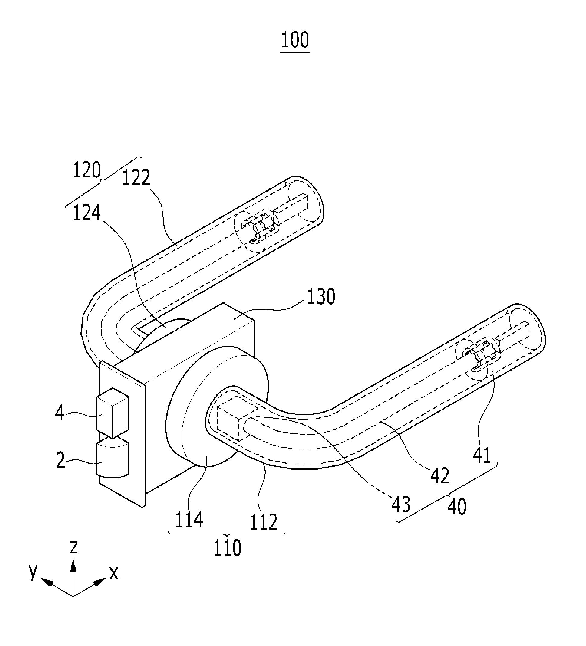
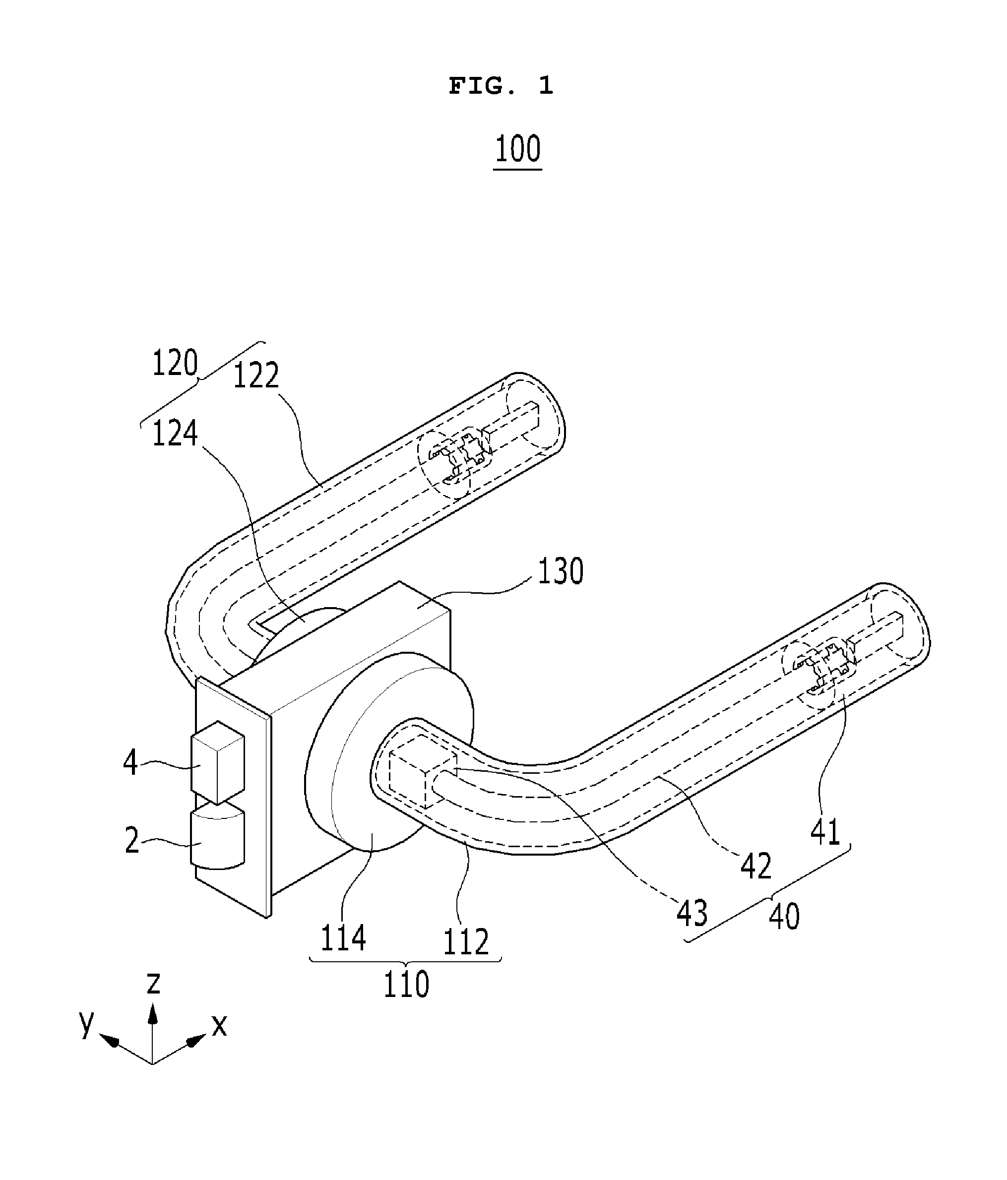
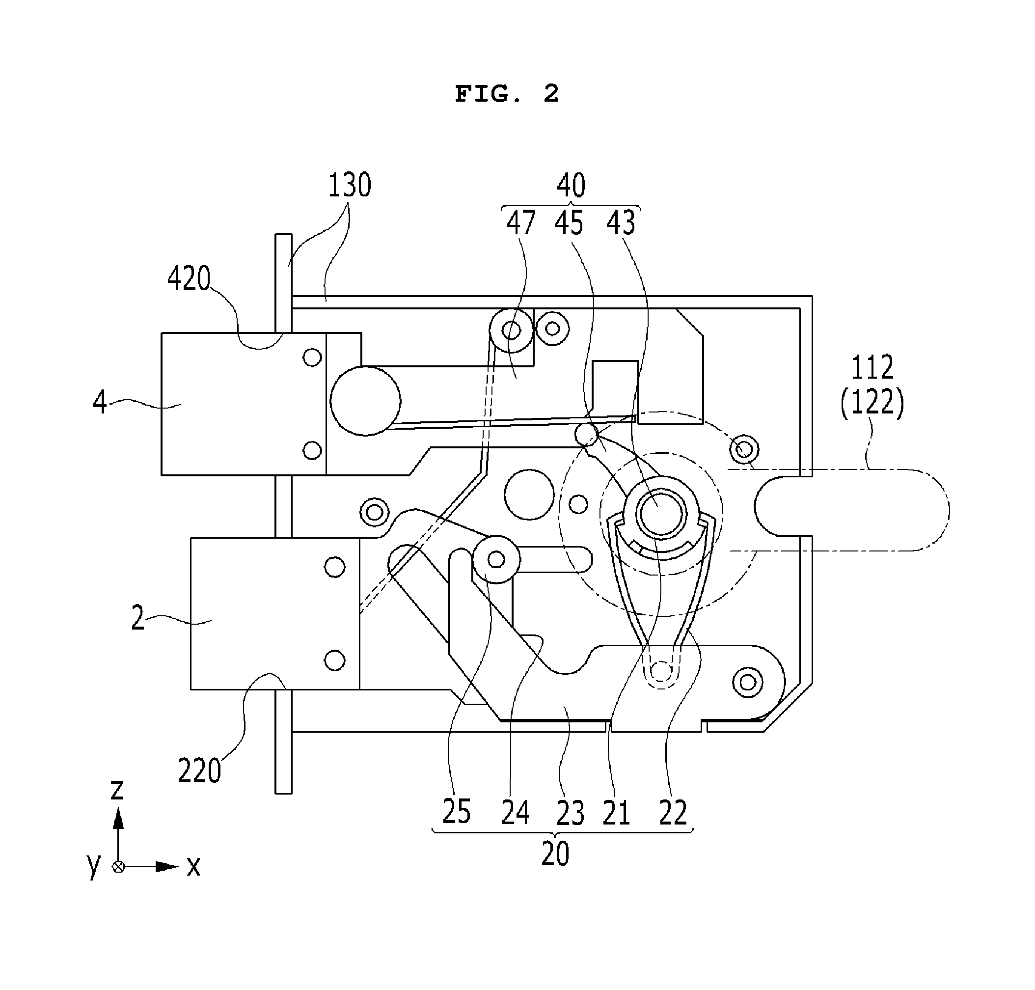
[0036]FIG. 1 is a perspective view of the lever type handle having the lock assembly according to the invention, and FIG. 2 is a schematic view for illustrating an example of a structure of the lock assembly for the lever type handle shown in FIG. 1.

[0037]With reference to FIG. 1 and FIG. 2, a lever type handle 100 having a lock assembly according to the embodiment of the invention includes handle structures 110 and 120 positioned at both sides of a door (not shown) to be operated by a user, and a case portion 130 is positioned between the handle structures 110 and 120. Lock assemblies 20 and 40 are positioned inside each of the handle structures 110 and 120 so that the door is opened and closed by the user through the operation of the handle structures 110 and 120.

[0038]The handle structures 110 and 120 include housing portions 114 and 124 installed to be adjacent to the door by fixing members(not shown) such as bolts and handle portions 112 and 122 rotatably coupled, respectively....

second embodiment

[0067]FIG. 5 is a perspective view of a lever type handle including a lock assembly according to the invention.

[0068]Referring to FIG. 5, a lever type handle 102 according to the second embodiment is applied to a sliding door 20 such as a window. That is, in the above embodiment, it is described and shown that the lever type handle is applied to a hinged door. On the other hand, in the second embodiment, a lock assembly for the lever type handle is applied to the sliding door 20. In this instance, handle structures 110a may be positioned at both side of the sliding door 20, respectively, or the handle structure 110a may be positioned at one side of the sliding door 20.

[0069]In the second embodiment, the dead lock member 4a positioned inside the sliding door 20 is protruded to maintain the locked state or is inserted into the sliding door 20 to release the locked state, by the rotation of the rotary shaft 43 through the key module 40. Since known various structures may be applied to ...

third embodiment

[0071]FIG. 6 is a perspective view of a door having a lever type handle including a lock assembly according to the invention.

[0072]As shown in FIG. 6, in a lever type handle 104 according to the third embodiment, the dead lock member prevents the rotation of the handle portion 112 or 122, not protruding to the outside. That is, when the key module 41 of a lock assembly for the lever type handle is rotated, the dead lock member (not shown) moves to a position for preventing the rotation of the handle portions 112 and 122. Then, the handle portions 112 and 122 cannot be rotated, and thus, the latch member 2 cannot be inserted into the case portion 103. Thus, the door can be kept closed.

[0073]Since known various structures may applied to the structure for preventing the rotation of the handle portions 112 and 122, the detail descriptions thereof will be omitted.


PUM


Abstract

A lock assembly for a lever type handle is disclosed. In the lock assembly for the lever type handle according to an aspect to the invention, the lever type handle is for opening and closing a door by a rotation of a handle portion. The lock assembly includes a key module rotated by a key member, wherein the key module being positioned in the handle portion, a rotary shaft rotated by a rotation of the key module and locking or unlocking the door through a dead lock member, and a rotation transmitter for transmitting the rotation of the key module to the rotary shaft.

Description

TECHNICAL FIELD[0001]The invention relates to a lever type handle and a lock assembly for the same.BACKGROUND ART[0002]Recently, as an interest in interior design increases, a shape of a handle is also diversified. Among handles of various types, a lever type handle is convenient, and has an excellent appearance. Therefore, the lever type handle is used for various doors, such as, a door of a room, a window, a front door, and so on.[0003]A lever type handle basically opens and closes a door, and, additionally locks the door by preventing the rotation of the lever type handle or by using a dead lock member such as a dead bolt. For this, a key way or a hole wherein an additional key is inserted is formed at a peripheral portion of the lever type handle or a front surface of the lever type handle.[0004]However, since the key way or the hole is formed at the peripheral portion of the lever type handle or the front surface of the lever type handle, a large area is necessary to perform an...

Claims


Application Information

Patent Timeline
Patent Type & Authority Patents(United States)
IPC IPC(8): E05B59/00E05B13/10E05B1/00E05B13/00E05B15/00E05B17/04E05B53/00
CPCE05B15/00E05B53/003E05B1/003E05B17/041E05B13/00Y10T70/5226Y10T70/573Y10T70/5765Y10T70/5796Y10T70/5832Y10T70/5973Y10T70/7486Y10T292/57Y10T292/82E05B1/00
Inventor KOH, YOUNGKYUN
Owner KOH YOUNGKYUN
Why Eureka
Try Eureka