Continuous winding equipment and continuous winding method for pipe with socket socket
A socket and pipe technology, applied in the field of continuous winding, can solve the problems of low processing efficiency and the inability of online one-time forming of pipe socket and socket, and achieve the effect of improving the forming efficiency
- Summary
- Abstract
- Description
- Claims
- Application Information
AI Technical Summary
Problems solved by technology
Method used
Image
Examples
Embodiment 1
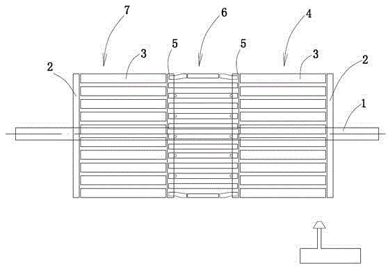
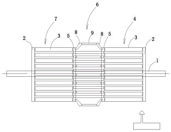
[0038] Embodiment 1: A continuous winding equipment for pipe with socket socket (see attached figure 1), including a winding unit molding device and a molten material extruder 18, the winding unit molding device includes two forming cages arranged on the same main shaft 1, the right end of the main shaft is the first forming cage 4, and the left end of the main shaft is the second forming cage Cage 7, a variable diameter mold 6 is arranged between the first forming cage and the second forming cage. The variable-diameter mold includes connecting discs on both sides. The two connecting discs are fixed with the main shaft to form a fixed disc 5. There are outwardly expanding outreaching roller shafts connected between the circumferences of the two fixing discs, and the outreaching roller shafts expand outward. Finally, the pipe socket winding part is formed (see attached figure 2 ), the length of the variable diameter die is equal to or greater than the sum of the lengths of th...
Embodiment 2
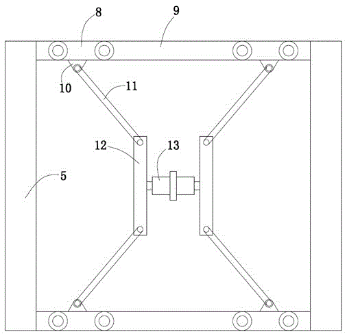
[0047] Embodiment 2: A continuous winding equipment for pipes with sockets (see attached figure 1 attached figure 2 attached Figure 5 attached Figure 6 ), the fixed discs at both ends of the variable diameter mold 6 can move relative to the axis of the main shaft, but cannot rotate relative to the main shaft. A rotating rod is connected between the two fixed disks of the variable-diameter mold, and the rotating rod drives the two fixed disks to approach each other. A short arm 8 is hinged on the fixed plate, and the hinge point is a fixed hinge point 15. The end of the short arm is hinged with an intermediate roller 9, and the hinge point is a swing hinge point 16. The distance between the swing hinge point and the axis of the main shaft is greater than the distance between the fixed hinge point and the The distance between the axis of the main shaft, the line between the fixed hinge point and the swing hinge point is inclined to the axis of the main shaft. When the two...
PUM
 Abstract
Description
Claims
Application Information
 - R&D
- Intellectual Property
- Life Sciences
- Materials
- Tech Scout
- Unparalleled Data Quality
- Higher Quality Content
- 60% Fewer Hallucinations
Browse by: Latest US Patents, China's latest patents, Technical Efficacy Thesaurus, Application Domain, Technology Topic, Popular Technical Reports.
© 2025 PatSnap. All rights reserved.Legal|Privacy policy|Modern Slavery Act Transparency Statement|Sitemap|About US| Contact US: help@patsnap.com


