
Movable center mechanism for formed grinding machine

A technology of gear grinding machine and top, applied in the direction of gear cutting machine, tailstock/top, gear teeth, etc. It can solve the problems that the top cannot be adjusted independently in the radial direction, and the top cannot be adjusted independently, so as to change the pressing force and reduce the resistance , the effect of reducing difficulty

Inactive Publication Date: 2014-01-15
浙江嘉力宝传动设备有限公司
View PDF7 Cites 0 Cited by
  • Summary
  • Abstract
  • Description
  • Claims
  • Application Information

AI Technical Summary

Problems solved by technology

[0006] The present invention also solves the defect in the prior art that the tip and the top screw sleeve are matched by a tapered surface, and the tip cannot be adjusted independently in the radial direction, and provides a movable tip mechanism of a forming gear grinding machine, which can be adjusted by adjusting the tip sleeve. Adjust the radial position of the tips, avoiding the problem of not being able to individually adjust the tips

Method used


Image

  • Movable center mechanism for formed grinding machine
  • Movable center mechanism for formed grinding machine

Examples


Embodiment

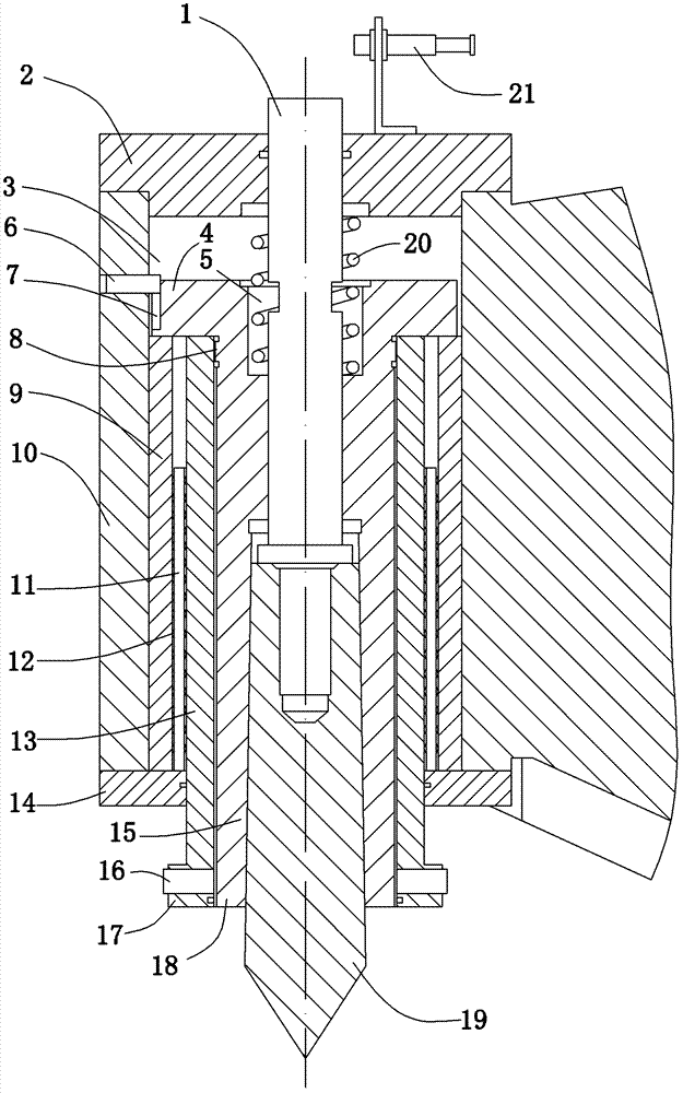
[0021] Example: a movable top mechanism of a forming gear grinding machine (see attached figure 1 ), including a bracket 10, the bracket is arranged on the machine tool of the gear grinding machine, the bracket is provided with an axial circular hole 3, and the two ends of the axial circular hole are respectively fixed with a top front connecting plate 14 and a top rear connecting plate 2. A middle circular hole is arranged in the middle, and a bolt hole is arranged in the middle of the rear end plate. A T-shaped center sleeve 15 is arranged in the axial circular hole. The center sleeve includes a disk portion 4 and a cylindrical portion 18, and the disk portion is perpendicular to the cylindrical portion. The outer diameter of the disc portion is matched with the inner diameter of the axial circular hole, the outer peripheral surface of the disc portion is provided with an axial chute 7, the corresponding part of the bracket is provided with a threaded hole, and the threaded ...


PUM


Abstract

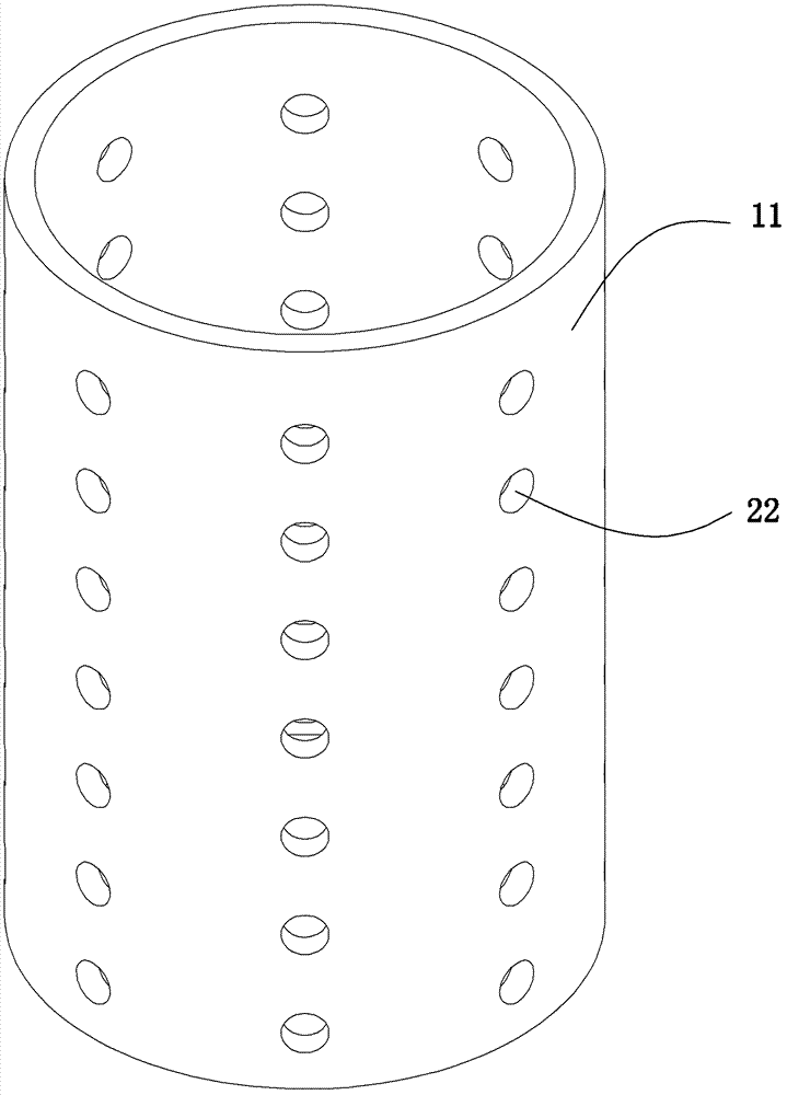
The invention relates to a movable center mechanism for a formed grinding machine. According to the movable center mechanism, the defects that the processing difficulty is increased and the processing cost is increased because a jackscrew sleeve is in surface contact with a bush in the prior art are overcome. An axial round hole is formed in a bracket; a center positioning sleeve is arranged in the axial round hole; a center sleeve is inserted into the center positioning sleeve; a center is arranged at one end part of the center sleeve; a center bolt is arranged at the middle of the center sleeve; one end of the center bolt is fixedly screwed with the center; the other end of the center bolt extends to the center and then is connected to the outside of a disk; a spring is sleeved on the center spring; and a plurality of steel beads are arranged between the center positioning sleeve and the inner wall of the axial round hole and are connected by a steel bead retainer in series. The center positioning sleeve is in rolling friction in the moving process, so that the resistance in moving is reduced and higher sensitivity is obtained; and the center positioning sleeve is in point contact with the axial round hole, so that the processing difficulty is reduced and the production cost is also reduced.

Description

technical field [0001] The invention relates to a machine tool accessory, in particular to a movable top mechanism for a forming gear grinding machine with high precision and precise adjustment of the pressing force. Background technique [0002] The top mechanism is an important clamping component in machine tool processing. When the machine tool processes some products with large lengths, the chuck of the machine tool and the top mechanism should be used together. The top mechanism can ensure that the center of rotation of the workpiece is always on the axis of rotation of the additional bed chuck. , to improve the machining accuracy. At present, the commonly used machine tool top mechanism is to assemble a set of radial bearings and a set of thrust bearings in the top. The radial bearing is used to support the rotation of the top, and the push bearing is used to bear the axial force in the work of the machine tool. The top of this type of machine tool mainly depends on t...

Claims


Application Information

Patent Timeline
Patent Type & Authority Patents(China)
IPC IPC(8): B23B23/04B23F23/06
Inventor 陈立新
Owner 浙江嘉力宝传动设备有限公司
Learn More