
A pipeline in-situ linear adjustment system and adjustment method

A linear adjustment and pipeline technology, used in tunnels, earth-moving drilling, tunnel lining, etc., can solve the problems of inapplicable pipe jacking, small sinking of pipes or tunnels, and failure to meet the height requirements of jacking pipes. Linear adjustment effect, good jacking effect, good water stop effect

Active Publication Date: 2019-04-16
SHANGHAI ROAD & BRIDGE (GRP) CO LTD
View PDF6 Cites 0 Cited by
  • Summary
  • Abstract
  • Description
  • Claims
  • Application Information

AI Technical Summary

Problems solved by technology

Although the injection of cement grout has an obvious effect on adjusting the structure of the pipeline or tunnel, the cement grout will solidify and harden. If it is used in the pipe jacking method, it will seriously damage the formation of the mud film and cause excessive resistance during the pipe jacking process.
Therefore, the traditional shield grouting method is not suitable for the alignment adjustment of the pipe jacking, and needs to be improved and perfected according to the characteristics of the pipe jacking method
[0010] 2. The traditional water stop device is not suitable for linear adjustment construction
[0012] 3. The amount of settlement is large, and a single method cannot meet the needs of in-situ adjustment
[0013] The traditional linear adjustment method is often aimed at a small amount of sinking of the pipeline or tunnel. When the adjustment amount of the pipeline exceeds a certain value, the single adjustment method often cannot meet the requirements for the height of the jacking pipeline.
[0014] At the same time, the means of adjusting the pipeline in the stratum crossing the river is often limited, and at the same time, the influence of the external water and soil pressure on the pipeline must also be considered during the adjustment process.
These factors are often not involved in previous engineering cases
[0015] 4. The geological conditions of cross-river pipelines are complex, there are very few related engineering cases, and there is a lack of corresponding theoretical research
Due to the influx of surrounding water and soil into the interior of the pipeline, the soil and strata around the pipeline are seriously lost, which leads to the subsidence of part of the pipeline structure. Due to the uneven subsidence of some pipe joints, the axis of the pipeline is bent and deformed.

Method used


Image

  • A pipeline in-situ linear adjustment system and adjustment method
  • A pipeline in-situ linear adjustment system and adjustment method
  • A pipeline in-situ linear adjustment system and adjustment method

Examples


Embodiment 1

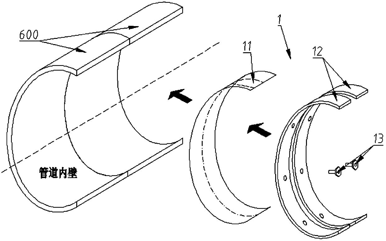
[0045] An in-situ linear adjustment system for pipelines includes a plurality of water stop devices 1 , jacking devices 2 and grouting devices 4 . The water stop device 1 is arranged at the junction of adjacent pipe joints in the sinking pipeline to fill the gap caused by the misalignment of the pipe joints 600, and can also play the role of water stop. The jacking device 2 is arranged in the pipeline for lifting the submerged pipe joint 600 to its original position, and the grouting device 4 is used for grouting the lower soil layer after the sunken pipe joint 600 is lifted.

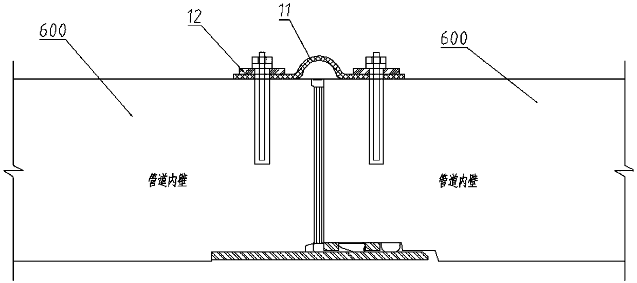
[0046] Such as figure 1As shown, the water stop device 1 adopts an internal expansion ring water stop device, and each internal expansion ring water stop device includes a rubber pad water stop 11 and two curved steel pressure plates 12, and the rubber pad water stop 11 has a certain width, and it fits on the inner walls of two adjacent and misaligned pipe joints 600, so that the rubber pad waterstop 1...

Embodiment 2

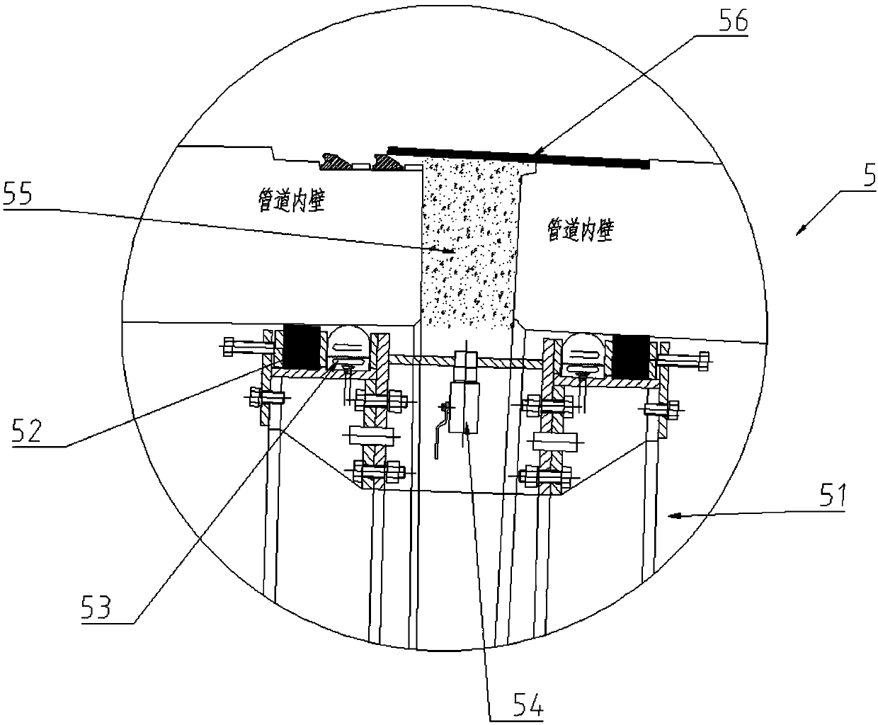
[0060] The difference between the second embodiment and the first embodiment is that the water stop device adopts the inflatable water stop device 5 instead of the internal expansion ring water stop device.

[0061] The inflatable water-stop device includes a steel collar 51 with a diameter slightly smaller than the inner diameter of the pipe, and an inflatable water-stop rubber belt 52 and a compressible water-stop packing 53 arranged on the peripheral surface of the steel collar 51. Both sides of the collar 51 in the axial direction are provided with an inflatable water-stop rubber belt 51 and a water-stop packing 53 to respectively cooperate with two adjacent pipe joints 600 so as to seal the gap at the joint of the pipe joints 600, and the The inflatable water-stop rubber belt 52 and the compressible water-stop packing 53 are squeezed between the steel collar 51 and the inner wall of the pipe to closely contact with the pipe wall so as to realize the water-stop effect.

[...


PUM


Abstract

The invention discloses a pipeline in-situ linear adjustment system. The system comprises sealing devices, grouting devices and a jacking device, the sealing devices are arranged at the joints of adjacent pipe sections of a pipeline, the grouting devices are arranged in sinking pipe sections and used for injecting slurry to the positions below the sinking pipe sections, the jacking device comprises a jacking beam and a plurality of hydraulic cylinders, wherein the jacking beam extends in the direction of the pipeline and is supported on the inner wall of the pipeline, the lower ends of the hydraulic cylinders are supported on the jacking beam and the upper ends of the hydraulic cylinders can abut against the inner wall of the pipeline, and a part of the jacking beam is located at a sinking section of the pipeline. According to the pipeline in-situ linear adjustment system, the jacking device is arranged, the pipeline can return back to an original position as much as possible through the jacking force of the hydraulic cylinders, and the effect of linear adjustment is improved.

Description

technical field [0001] The invention relates to the field of in-situ linear adjustment of underground pipelines such as crossing rivers, in particular to an in-situ linear adjustment system and an adjustment method. Background technique [0002] In underground pipeline or tunnel engineering, for pipelines that are under construction or have been constructed, due to external factors, the pipe joints that make up the pipeline will shift or sink, resulting in deformation of the original linear pipeline. [0003] The in-situ linear adjustment construction method of the pipeline (hereinafter referred to as the "linear adjustment method") refers to the use of certain equipment and technical means to adjust the position of the pipe joints that have moved, so that the deformed pipeline returns to a straight line state. [0004] The domestic linear adjustment method is mainly used in the "subway shield tunnel", and the main application method is grouting technology, that is, grouting...

Claims


Application Information

Patent Timeline
Patent Type & Authority Patents(China)
IPC IPC(8): E21D15/44E21D11/10E21D11/38
CPCE21D11/10E21D11/38E21D15/44
Inventor 王剑锋吕品黄莹峰梁辉赵强
Owner SHANGHAI ROAD & BRIDGE (GRP) CO LTD
Learn More