A light crawler lateral positioning structure

A technology of lateral positioning and track, which is applied to tracked vehicles, motor vehicles, transportation and packaging, etc. It can solve the problems of insufficient lateral rigidity of light crawler, achieve the effect of improving overall walking performance, increasing lateral rigidity, and not easy to take off the belt

Active Publication Date: 2016-05-25
杨存俭
View PDF6 Cites 0 Cited by
  • Summary
  • Abstract
  • Description
  • Claims
  • Application Information

AI Technical Summary

Problems solved by technology

[0003] The purpose of the present invention is to solve the above-mentioned deficiencies in the prior art, thereby providing a lateral positioning structure that can avoid the lateral displacement between adjacent track joints to the greatest extent, improve the lateral rigidity of the light track, and solve the problem of the existing light track lateral displacement. Insufficient steel defect

Method used


Image

  • A light crawler lateral positioning structure
  • A light crawler lateral positioning structure

Examples


Embodiment Construction

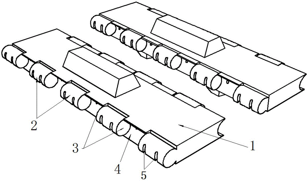
[0009] Below in conjunction with accompanying drawing, the present invention is described in detail: as figure 1 As shown, in the embodiment of the light-duty track lateral positioning structure, it includes nine positioning protrusions 2 arranged in dislocation on both sides of the track joint 1, the positioning protrusions are cylindrical, and the positioning protrusions formed between two adjacent positioning protrusions 2 Groove 4, the two end faces of positioning convex body 2 are positioning surfaces 3, and radially are provided with the cable hole 5 that passes for drag cable, and positioning convex body 2 also can be circular tube shape, not shown in the figure.

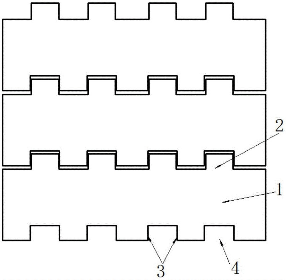
[0010] Such as figure 2 As shown, after two track joints 1 are combined, the positioning protrusion 2 of one track joint 1 is embedded in the positioning groove 4 of the other track joint 1 to form a complementary shape. The positioning surface 3 of one track joint 1 is in contact with the positioning surfa...


PUM


Abstract

The invention relates to a transverse positioning structure of a light caterpillar band. The transverse positioning structure mainly comprises three or more positioning protrusions arranged on the two sides of caterpillar band segments in a staggered mode, wherein each positioning protrusion is cylindrical or in the shape of a round tube, stay rope holes used for stay ropes to pass through are formed in the positioning protrusions in the radial direction, and the two end faces of each positioning protrusion serve as positioning faces; a positioning groove is formed between every two adjacent positioning protrusions; after every two caterpillar band segments are combined, the positioning protrusions on one caterpillar band segment are embedded into the positioning grooves in the other caterpillar band segment so as to form complementation; after the two caterpillar band segments are combined, the positioning faces of one caterpillar band segment make contact with the positioning faces of the other caterpillar band segment, and the transverse positions of the caterpillar band segments are limited. The transverse positioning structure of the light caterpillar band has the advantages that the transverse displacement between every two adjacent caterpillar band segments can be limited to the greatest extent, transverse rigidity of the light caterpillar band is improved, the caterpillar band cannot easily fall off in work, and the overall traveling performance of the light caterpillar band is improved.

Description

technical field [0001] The invention relates to a crawler belt device, in particular to a light crawler belt lateral positioning structure. Background technique [0002] Tracks are an essential walking part of tracked vehicles, just like car tires. There are two types of track composed of track joints: articulated track and flexible track. ZL200810062883.3, which was previously applied by the applicant and has been authorized, is titled "A Lightweight Crawler". It discloses a structure of a flexible joint type crawler. The crawler still has the defect of insufficient transverse rigidity. Contents of the invention [0003] The purpose of the present invention is to solve the above-mentioned deficiencies in the prior art, thereby providing a lateral positioning structure that can avoid the lateral displacement between adjacent track joints to the greatest extent, improve the lateral rigidity of the light track, and solve the problem of the existing light track lateral disp...

Claims


Application Information

Patent Timeline
Patent Type & Authority Patents(China)
IPC IPC(8): B62D55/205
Inventor 杨存俭
Owner 杨存俭
Why Eureka
Try Eureka