Water heater water tank with laterally-arranged automatic control water feeding device

A water heater water tank, water heater technology, applied in heating devices, fluid heaters, solar thermal devices, etc., can solve problems such as electromagnetic valve corrosion, reducing the scope of application of water heaters, and increasing failure rates.

Active Publication Date: 2014-08-20
HAIER GRP CORP +1
View PDF7 Cites 4 Cited by
  • Summary
  • Abstract
  • Description
  • Claims
  • Application Information

AI Technical Summary

Problems solved by technology

However, due to the above method, setting the solenoid valve on its top will easily cause the solenoid valve to be corroded b

Method used


Image

  • Water heater water tank with laterally-arranged automatic control water feeding device
  • Water heater water tank with laterally-arranged automatic control water feeding device
  • Water heater water tank with laterally-arranged automatic control water feeding device

Examples


Embodiment 1

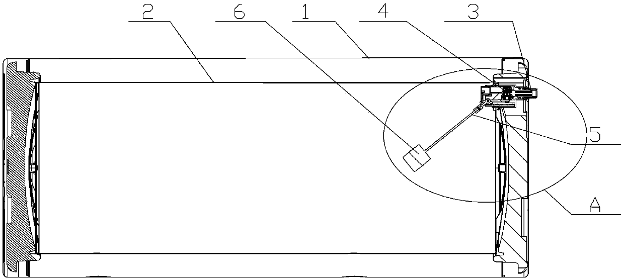
[0026] Such as figure 1 As shown, this embodiment introduces a water heater tank with a side-mounted automatic control water supply device, including: a water tank shell 1 and an inner tank 2 arranged in the outer shell 1, and the upper part of the side wall of the inner tank 2 is provided with an inlet water pipe3. The water inlet pipe 3 is provided with a water stop valve 4; the water stop valve 4 communicates with the floating ball 6 that is movably arranged at the water surface of the inner tank 2 through a switch device 5 that can control the working state of the water stop valve. connect.

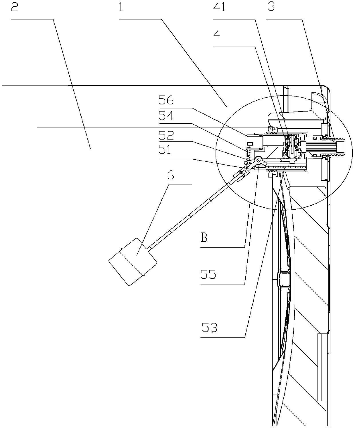
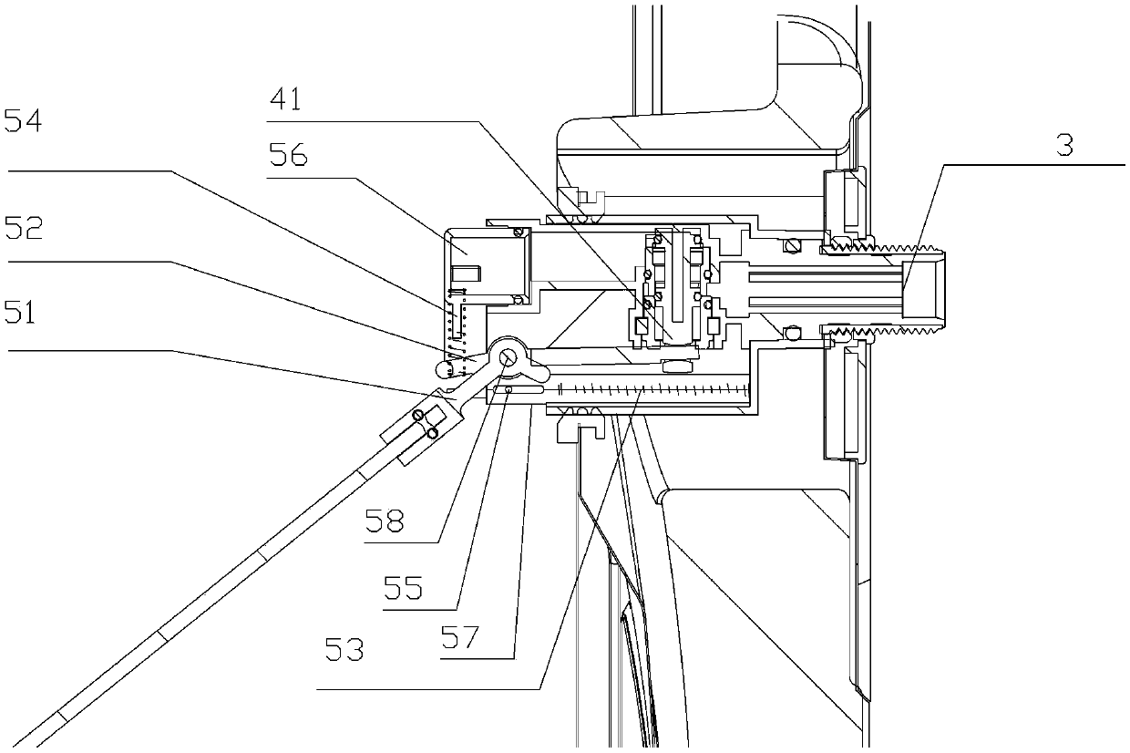
[0027] Such as figure 2 with image 3 As shown, in this embodiment, the water heater tank is provided with a mounting seat 57 along the axis of the water inlet pipe 3 in conjunction with the water stop valve 4 . The water stop valve 4 is arranged at the contact between the mounting seat 57 and the water inlet pipe 3 . The water stop valve 4 is provided with a control shaft 41 th...


PUM


Abstract

The invention relates to the field of water heaters, in particular to a water heater water tank with a laterally-arranged automatic control water feeding device. The water tank comprises a water tank outer shell and an inner container arranged in the outer shell, a water inlet pipe is arranged on the side wall of the inner container, a water stopping valve is arranged on the water inlet pipe, and the water stopping valve is connected with a switch device for controlling the water stopping valve to be opened and closed. The switch device comprises a power source, a transmission component and a floating ball control component, the power source provides power through elastic force of itself, the transmission component transmits power to control the water stopping valve to be opened and closed, and the floating ball control component controls the power source and the transmission component to be connected and disconnected. When a floating ball is arranged at the position filled with water/the water supplementing position, the floating ball control component controls the power source and the transmission component to be disconnected/connected, and therefore the opening and closing states of the water stopping valve are controlled, and the functions of automatically stopping the water feeding process when the water heater is filled with water, and the function of automatically feeding the water are achieved. The floating ball is arranged on the side portion of the water tank to automatically control the water feeding device, and the use corrosion and aging conditions caused by the fact that the water stopping valve is soaked in the water for a long time are avoided.

Description

technical field [0001] The invention relates to a water heater water tank in the field of water heaters, in particular to a water heater water tank with a side-mounted automatic control water filling device. Background technique [0002] At present, solar automatic water supply and water full automatic stop are generally realized by controlling the water supply solenoid valve with a controller and sensor or by using a lower float valve configuration. But adopt most of schemes of above-mentioned device, all can't solve the poor water quality sediment clogging pipeline problem. In the water tank configured with a bottom-mounted automatic float valve, the valve body is usually installed inside the water tank and combined with the bottom of the tank liner. Self-stop, but because the main body is in the water, the floating ball and the valve body will be corroded during long-term use, and the valve body will be blocked by scale precipitation for a long time and cannot enter wate...

Claims


Application Information

Patent Timeline
IPC IPC(8): F24H9/00F24H9/20F24J2/46
CPCY02E10/40
Inventor 吴绍杰闫苇
Owner HAIER GRP CORP
Why Eureka
Try Eureka