
X-band high power microwave integrated radiation field measurement system

A high-power microwave and measurement system technology, which is applied in the field of high-power microwave radiation field measurement devices, can solve problems such as lack of attenuation adjustment capability, influence on the reliability of measurement results, and interference with the dynamic range of measurement, so as to improve the dynamic range of measurement and strengthen Electromagnetic protection ability, easy and fast deployment effect

Inactive Publication Date: 2016-06-01
NO 63655 TROOPS OF THE CHINESE PEOPLES LIBERATION ARMY
View PDF12 Cites 0 Cited by
  • Summary
  • Abstract
  • Description
  • Claims
  • Application Information

AI Technical Summary

Problems solved by technology

The basic composition of the current high-power microwave radiation field measurement system is shown in the document "Chen Yu. Research on Several Issues in High-power Microwave Power Measurement by Far-field Method [D]. Master's Thesis of National University of Defense Technology, 2005 (P6~P7). " As mentioned, the composition of this type of system faces the following problems: First, there is a weak link in electromagnetic protection, and the strong electromagnetic environment is easy to interfere with the measurement results; The reliability of the results has been affected; the third is that it does not have the ability to adjust the attenuation, and the measurement dynamic range is small
[0003] The other is the measurement system based on waveguide system probe coupling, such as the literature "Qu Jin, Liu Qingxiang, etc. High-power microwave radiation field power density measurement system [J]. Strong Laser and Ion Beam, 2004, 16 (1) ,77~80." As stated, this type of system also has problems such as being susceptible to external electromagnetic field interference and small dynamic range of measurement.

Method used


Image

  • X-band high power microwave integrated radiation field measurement system
  • X-band high power microwave integrated radiation field measurement system
  • X-band high power microwave integrated radiation field measurement system

Examples


Embodiment Construction

[0034] The present invention will be further described below in conjunction with the accompanying drawings and embodiments.

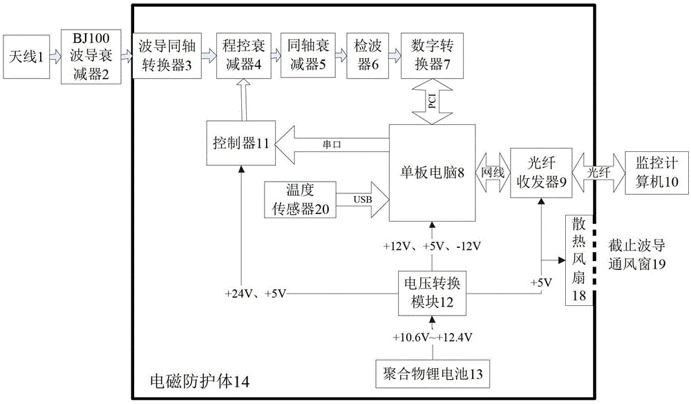
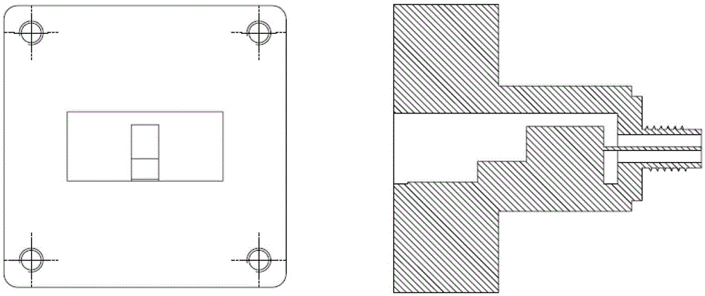
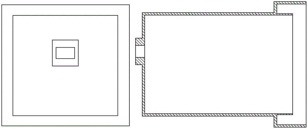
[0035] Such as figure 1 As shown, the high-power microwave radiation field signal enters the measurement system from the antenna 1, passes through the BJ100 waveguide attenuator 2, the waveguide-coaxial converter 3 (BJ100-SMA), the programmable attenuator 4 and the coaxial attenuator 5, and is detected by the detector 6. Detect the envelope waveform of the pulse signal. After the waveform is collected by the digital converter 7, it is sent to the single-board computer 8 as the processing computer through the PCI interface for storage. After the measurement system is strictly calibrated, the amplitude of the waveform is The power density value of the radiation field can be calculated. Considering the power capacity of the waveguide coaxial conversion 3 and its back-end system, the average power of the signal entering the device should be controlled not ...


PUM


Abstract

The invention provides an X-wave band high-power microwave integration radiation field measuring system. After being received by an antenna, a high-power microwave radiation field signal is processed by power attenuation by a waveguide attenuator and is successively transmitted to a programmable attenuator and a coaxial attenuator by a waveguide coaxial transducer to carry out power attenuation; a detector detects an envelop waveform of the signal and a digital converter carries out acquisition; the signal is transmitted to a single-board computer; and a monitoring computer uses a fiber optical transceiver to carry out monitoring on the digital converter and a temperature sensor; and the digital converter and the programmable attenuator are controlled. According to the invention, the system is integrated with functions of electromagnetic protection, attenuation adjustment, signal detection, data acquisition and process, remote controlling, and optical fiber data transmission and the like. The system with the compact structure is simple and can be carried conveniently; and rapid development of the external field measurement can be realized conveniently. The electromagnetic protection capability of the whole system is improved; the dynamic range of measurement is increased; and the system well adapts to measurement of radiation fields with different power levels.

Description

technical field [0001] The invention relates to a high-power microwave radiation field measuring device. Background technique [0002] High power microwave external field measurement system plays an important role in parameter measurement and diagnosis in high power microwave research. The basic composition of the current high-power microwave radiation field measurement system is shown in the document "Chen Yu. Research on Several Issues in High-power Microwave Power Measurement by Far-field Method [D]. Master's Thesis of National University of Defense Technology, 2005 (P6~P7). " As mentioned, the composition of this type of system faces the following problems: First, there is a weak link in electromagnetic protection, and the strong electromagnetic environment is easy to interfere with the measurement results; The reliability of the results has been affected; the third is that it does not have the ability to adjust the attenuation, and the measurement dynamic range is smal...

Claims


Application Information

Patent Timeline
Patent Type & Authority Patents(China)
IPC IPC(8): G01R29/08G01R21/133
Inventor 史鹏飞蒋廷勇刘小龙李鹏辉闫军凯叶虎景洪晏峰
Owner NO 63655 TROOPS OF THE CHINESE PEOPLES LIBERATION ARMY
Learn More