Method and device for finishing workpieces

A technology for finishing and workpieces, applied in the field of non-rotationally symmetrical components, it can solve the problems of a lot of finishing time, inaccurate self-guided support of finishing tools, and inability to remove, and achieves the effect of preventing wet grinding.

Inactive Publication Date: 2014-08-20
美艾格工业自动化系统股份有限公司
View PDF7 Cites 11 Cited by
  • Summary
  • Abstract
  • Description
  • Claims
  • Application Information

AI Technical Summary

Problems solved by technology

[0035] - During the fine longitudinal turning of the bearing position, there has hitherto been the problem that turning tools with different bends are required for turning the lower left and lower right parts, and therefore an unavoidable step of usually 10 to 30 μm is required between the two machines Provided in transitional sections of machining positions where this step cannot be efficiently removed by finishing alone, since material removal is required for this step several times as long due to the relatively imprecise self-guided support of the finishing tool , requires a lot of finishing time

Method used


Image

  • Method and device for finishing workpieces
  • Method and device for finishing workpieces
  • Method and device for finishing workpieces

Examples


Embodiment Construction

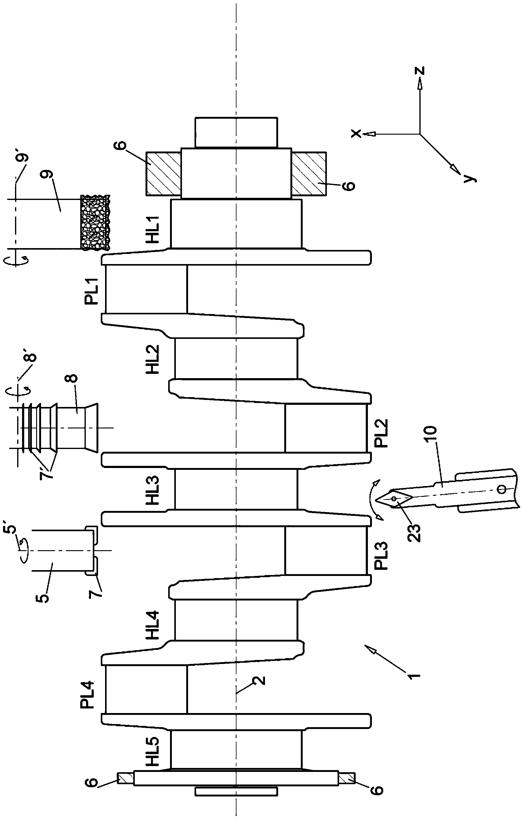
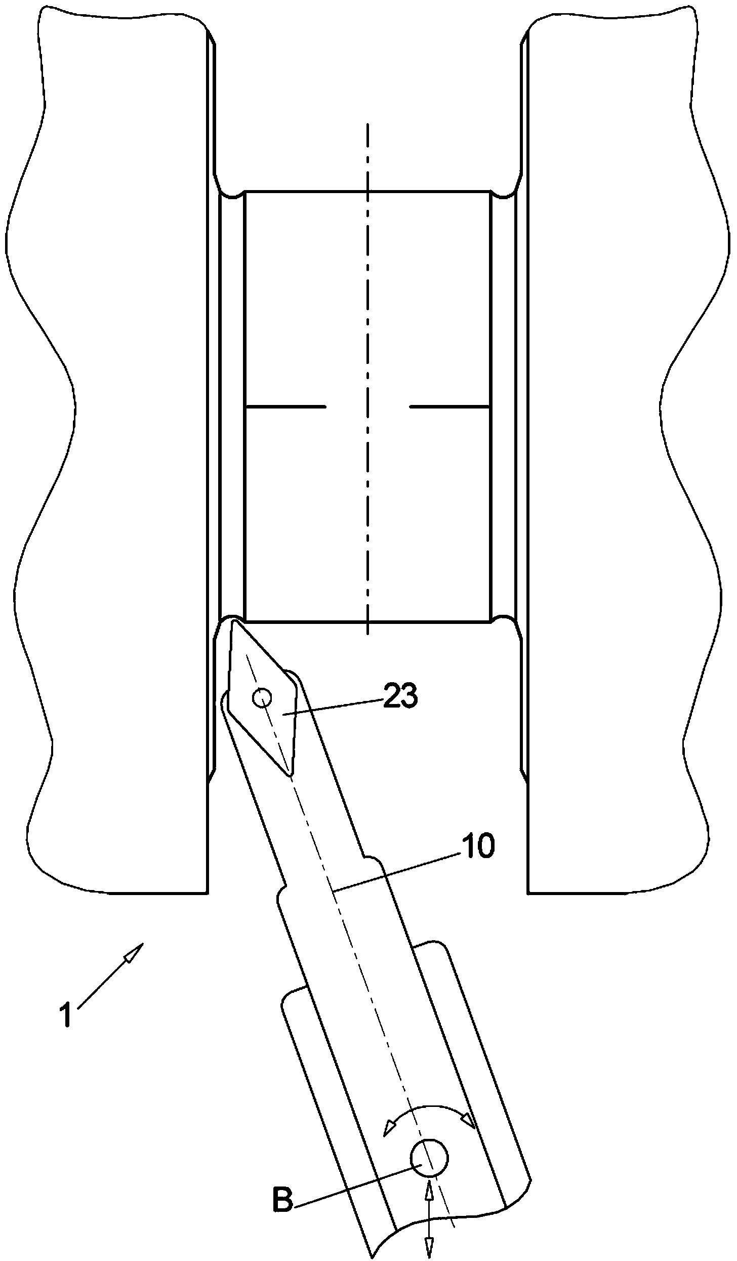
[0103] Figure 1a Illustrated is a side view of a typical crankshaft 1 of a four-cylinder combustion engine, wherein there are thus four eccentric elevator-or rod bearings PL1 to PL4 and a total of 5 main bearings HL1 to HL5 arranged adjacent thereto, wherein The main bearings are arranged on the subsequent axis of rotation (Z axis of the crankshaft), so by radial clamping by means of the jaws 6 at the flange 4 at one end and the pinion 3 at the other end of the crankshaft 1, The crankshaft 1 is clamped in a lathe (not described in more detail) on said rotational axis, which is also designated as rotational axis 2 in the illustration of FIG. 1 .

[0104] In particular, the invention relates to the machining of the enclosing surfaces of the bearing, and thus the main bearing, as well as the rod bearing including adjacent sides (so-called mirror surfaces).

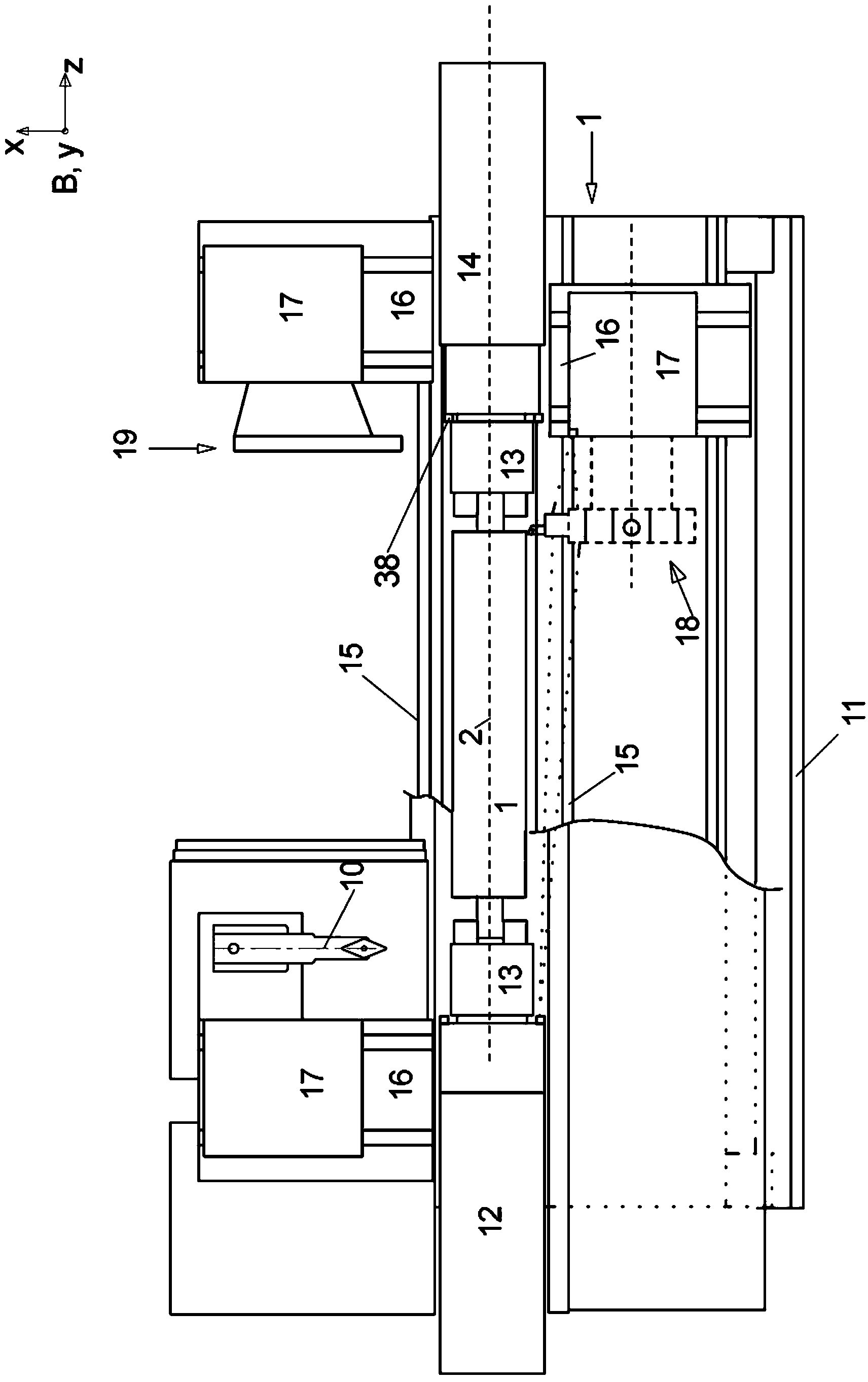
[0105] Above and below crankshaft 1, the machine tool is shown in an exemplary manner from top left to right:

[0106] - ...


PUM

PropertyMeasurementUnit
surface roughnessaaaaaaaaaa

Abstract

The aim of the invention is to shorten the process chain during the material-removing machining of in particular a crankshaft (1) following the rough machining and substantially after hardening. In order to achieve said aim, it is proposed, according to the invention, to combine peripheral rotary milling as a first step and subsequent dry grinding as a second step.

Description

technical field [0001] The invention relates to a method and method for the machining of rotationally symmetrical and non-rotationally symmetrical components, in particular crankshafts, and the mass production of crankshafts (crankpin bearings and journal bearings), especially bearing surfaces, to usable conditions and device, so the condition is that the crankshaft can be installed in the engine without removing additional material at the bearing surfaces. [0002] The bearing surface is thus an enveloping surface, thus the width of the bearing, and also a so-called beam surface, thus a surface adjacent to the bearing width eg for axial support. Background technique [0003] Crankshafts, especially crankshafts with multiple cylinders for automotive engines, are known to be unstable workpieces during machining and are therefore difficult to machine. In addition to the axial bearing width, the dimensional fit of the finished crankshaft is primarily determined by evaluating t...

Claims


Application Information

Patent Timeline
Patent Type & Authority Applications(China)
IPC IPC(8): B23P13/00B23P23/04B23Q39/02B24B5/42B23H9/00B23H3/00B23B5/18B23C3/06B23D37/00B23K26/00
CPCB23H2300/10B23P23/04B23H9/00B23P2700/07B24B1/00B23K2201/005B23P13/00B23H3/00B24B5/42B23Q39/023B23K2101/005Y10T29/17Y10T29/49286B23K26/356B23C3/06B23C2215/20B23C2220/64
Inventor 利奥·施瑞博尔马蒂亚斯·韦博
Owner 美艾格工业自动化系统股份有限公司
Why Eureka
Try Eureka