Washing machine

A washing machine and laundry technology, which can be applied to other washing machines, washing devices, cabinets/cases/drawer parts, etc., and can solve the problems of increased water volume, wrong display, and easy intrusion of foreign objects.

Active Publication Date: 2014-08-20
PANASONIC CORP
View PDF10 Cites 1 Cited by
  • Summary
  • Abstract
  • Description
  • Claims
  • Application Information

AI Technical Summary

Problems solved by technology

[0019] However, in the structure of the conventional washing machine, when the gap between the operation panel 109 and the abutting portion 117 of the accommodating portion 106 becomes large due to processing deviations of components, etc., the amount of water flowing into the accommodating portion 106 increases, making it difficult to reliably Waterproofing of the operating substrate 105
[0020] In addition, if

Method used


Image

  • Washing machine
  • Washing machine
  • Washing machine

Examples


Embodiment approach 1

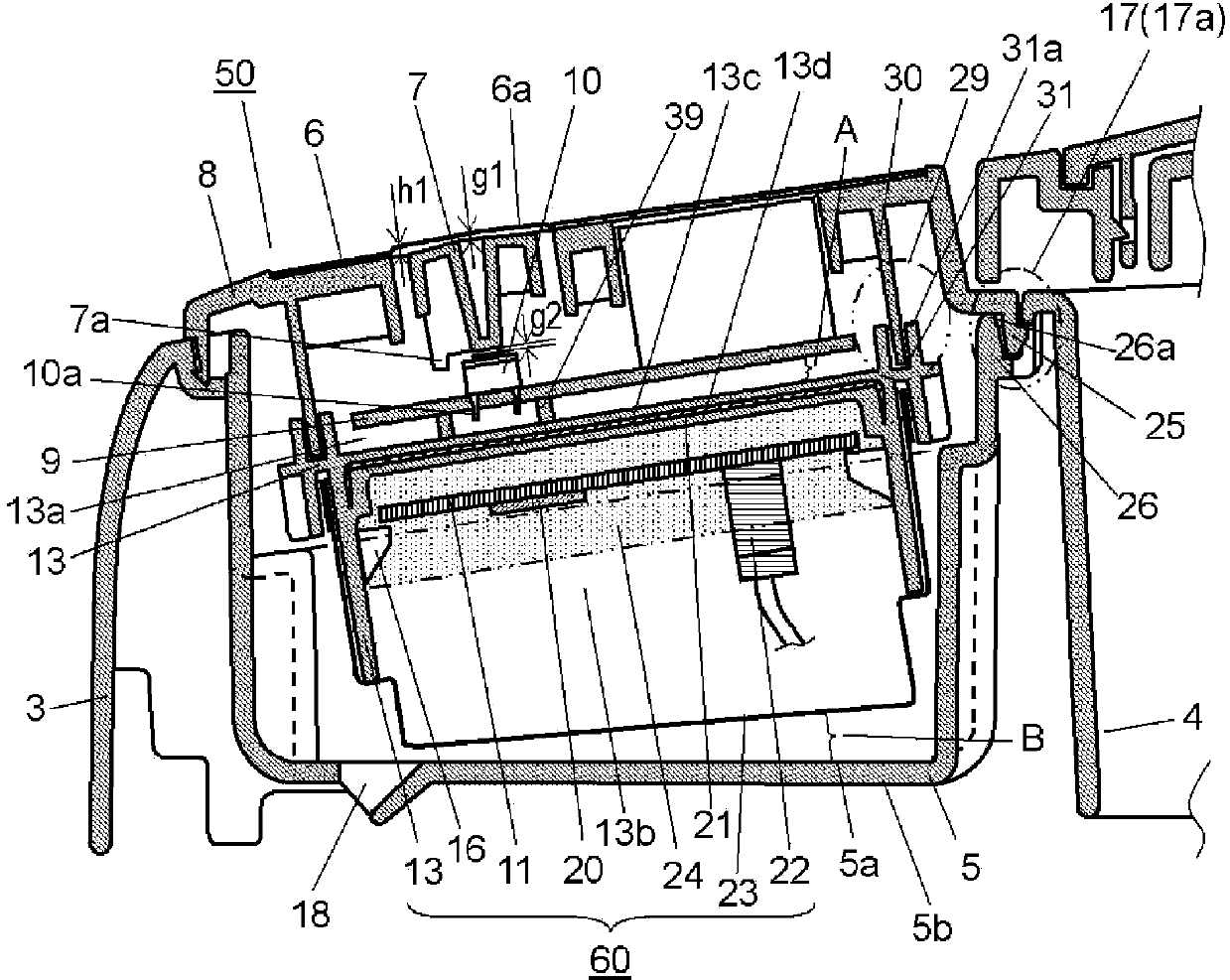
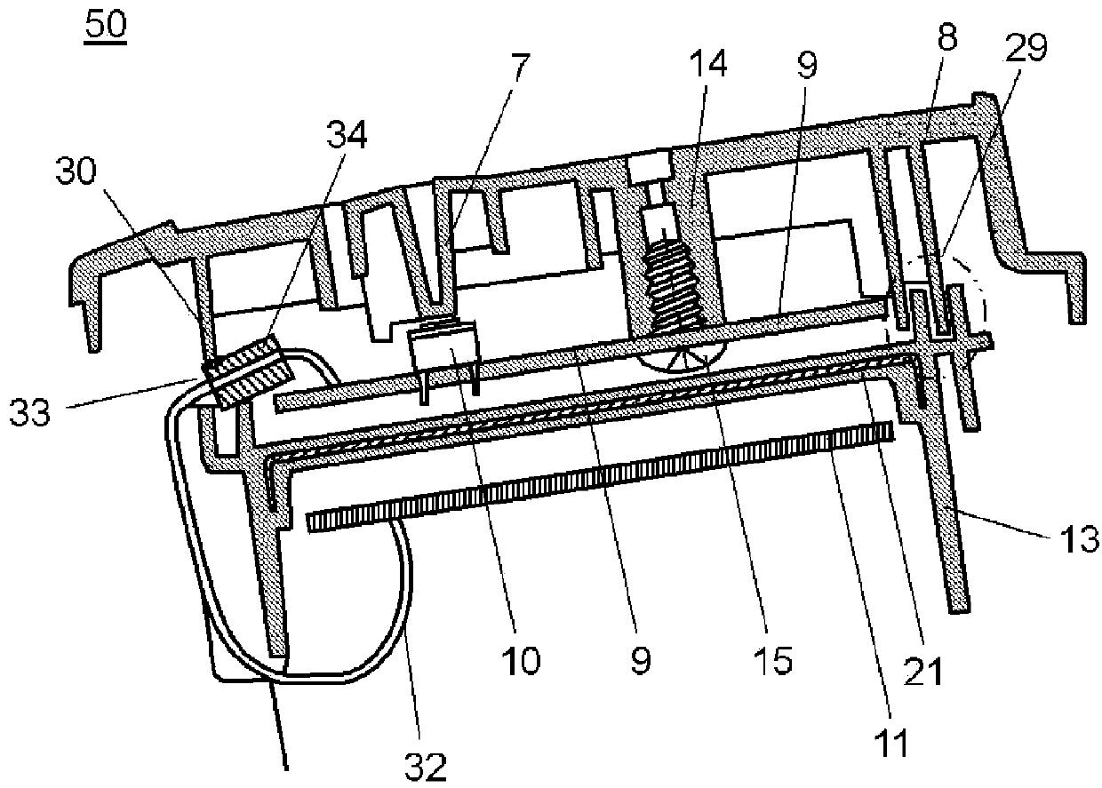
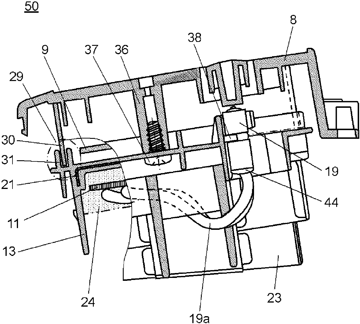
[0040] Below, use Figure 1 to Figure 6The power supply unit, the operating device, and the washing machine provided with the power supply unit and the operating device in Embodiment 1 of the present invention will be specifically described. In addition, below, a vertical washing machine will be described as an example.

[0041] figure 1 It is a sectional view of main parts around the power supply unit and the operation unit of the washing machine in Embodiment 1 of the present invention. figure 2 It is a sectional view of main parts of the washing machine. image 3 It is a sectional view of main parts of the washing machine. Figure 4 It is a sectional view of main parts of the washing machine. Figure 5 It is an upper sectional view of the washing machine. Figure 6 It is a sectional view of main parts of the washing machine.

[0042] like Figure 1 to Figure 6 As shown, the washing machine of this embodiment at least includes: a washing and dehydrating tank 1 (here...

Embodiment approach 2

[0135] Below, use Figure 8 A power supply unit, an operating device, and a washing machine including the power supply unit and the operating device in Embodiment 2 of the present invention will be described. In addition, below, similarly to Embodiment 1, a vertical washing machine will be described as an example.

[0136] Figure 8 It is a cross-sectional view of main parts around the power supply unit and the operation unit of the washing machine in Embodiment 2 of the present invention.

[0137] That is to say, the difference between the washing machine of this embodiment and Embodiment 1 is that, instead of the power supply device constituting a part of the operation device, the boat-shaped protective case formed by insert-molding the first non-combustible cover is replaced by the boat-shaped protective case and the power supply. A non-combustible member is provided between the substrates. In addition, description of the same structural elements, functions, etc. as thos...


PUM


Abstract

This washing machine is provided with a washing machine main body, an inner tank, and an upper outer contour (3), and is provided with: an operation panel (8) provided to the upper outer contour (3); an operation board (9); a protective case (13) that protects the operation board (9); a housing section (5) having a bottom section (5a) that houses the protective case (13); and a waterproofing section that waterproofs the operation board (9). Also, the waterproofing section has: a dam section (17a); and a water removal hole (18) provided to the bottom section (5a) of the housing section (5), and the opening area of the water removal hole (18) has a configuration that is larger than the area of a gap formed at the dam section (17a). As a result, it is possible to realize a washing machine that waterproofs the operation board (9) and has superior reliability, preventing erroneous display and erroneous operation.

Description

technical field [0001] The present invention relates to a washing machine having an operation unit such as an operation panel as part of the outer casing. Background technique [0002] In the past, a washing machine generally has: a washing and dehydrating tank (hereinafter referred to as "inner tank") for washing and dehydrating inside the body; On the outer shell of the body near the inlet for taking out (for example, refer to Patent Document 1). In addition, the washing machine having the above-mentioned structure is sometimes installed outdoors due to the limitation of the living environment. [0003] Below, use Figure 9 to Figure 12 The configuration of the conventional washing machine described in Patent Document 1 will be described. [0004] Figure 9 It is a side sectional view of a conventional washing machine. Figure 10 It is an exploded explanatory drawing of a conventional washing machine. Figure 11 It is a sectional view of main parts around the operatin...

Claims


Application Information

Patent Timeline
IPC IPC(8): D06F39/00D06F39/12H05K5/00H05K5/02D06F34/34
CPCD06F39/12D06F39/005D06F2105/08D06F34/34D06F2101/00
Inventor 前田一宪
Owner PANASONIC CORP
Why Eureka
Try Eureka