Lubricant dispenser

A lubricant and distributor technology, applied in the direction of engine lubrication, engine components, mechanical equipment, etc., can solve problems such as increasing current consumption, and achieve the effect of reducing current consumption, improving energy efficiency, and reducing battery capacity

Active Publication Date: 2014-08-20
PERMA TEC
View PDF8 Cites 0 Cited by
  • Summary
  • Abstract
  • Description
  • Claims
  • Application Information

AI Technical Summary

Problems solved by technology

Motor based load increases current draw

Method used


Image

  • Lubricant dispenser
  • Lubricant dispenser
  • Lubricant dispenser

Examples


Embodiment Construction

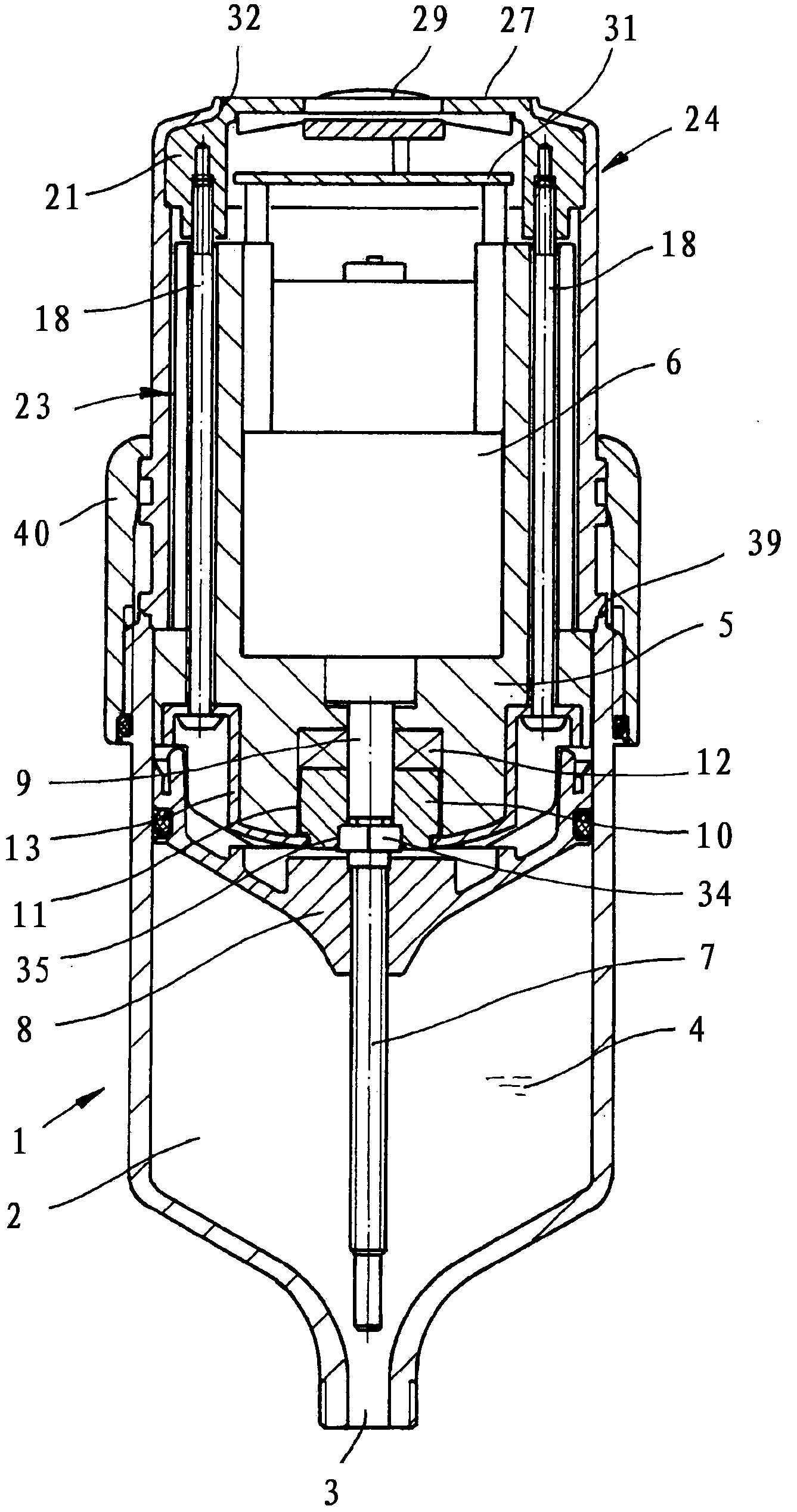
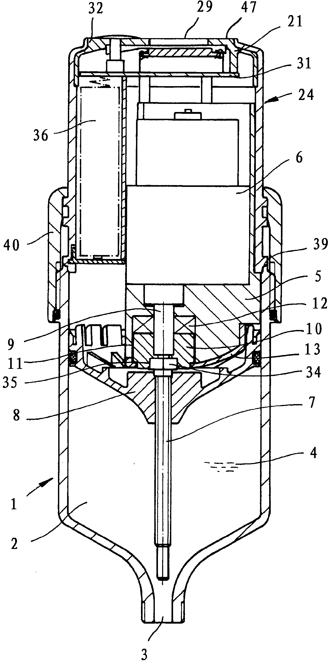
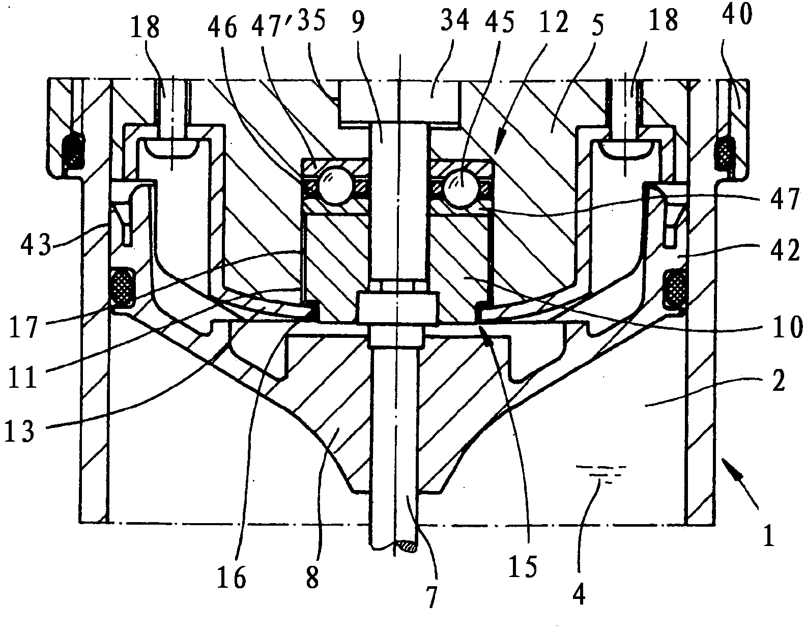
[0023] The basic structure of the lubricant dispenser shown in the accompanying drawings includes: a lubricant cartridge 1, which has a lubricant storage chamber 2 provided with a lubricant 4 outlet 3; a bracket that is detachably connected to the lubricant cartridge 1 5. The bracket accommodates a battery-powered motor 6 for driving the screw 7; a piston 8 connected with the screw 7 for pressing out lubricant. The motor 6 , which in the lubricant distributor shown here is an electric gear motor, has an output shaft 9 which is connected to the screw 7 by means of an adapter 10 . The adapter 10 is mounted rotatably in a receiving space 11 of the holder 5 which is open towards the lubricant cartridge 1 . A rolling bearing 12 is provided as a bearing for the adapter 10 , which is arranged between the carrier 5 and the adapter 10 . The adapter 10 is secured against falling out of the receiving space 11 in the axial direction by means of restraint means 13 secured to the bracket 5...


PUM


Abstract

The invention relates to a lubricant dispenser having a lubricant cartridge (1), which has a lubricant storage space (2) having an outlet opening (3) for lubricant (4), a carrier (5) which is connected to the lubricant cartridge (1) in a detachable manner and accommodates a battery-operated motor (6) for driving a spindle (7), and a plunger (8) connected to the spindle (7) for ejecting the lubricant (4), wherein an output shaft (9) of the motor (6) is connected to the spindle (7) by means of an adapter (10) and wherein the adapter (10) is mounted in a rotationally movable manner in an accommodation space (11) of the carrier (5) that is open towards the lubricant cartridge (1). A rolling bearing (12), which is arranged between the carrier (5) and the adapter (10), is provided as the bearing of the adapter (10). The adapter (10) is secured axially against falling out of the accommodation space by means of a retaining means (13) that is fastened to the carrier (5) and preferably designed as a lid.

Description

technical field [0001] The invention relates to a lubricant dispenser, comprising: a lubricant cylinder, the lubricant cylinder has a lubricant storage chamber provided with a lubricant discharge port; a bracket detachably connected with the lubricant cylinder, the bracket accommodates a battery-powered motor; and a piston connected to the screw for extruding the lubricant, where the output shaft of the motor is connected to the screw by means of an adapter and the adapter is rotatably mounted in a housing of the bracket open to the lubricant cartridge in space. Background technique [0002] Such a lubricant distributor is known from practice and from DE 29 715 808 U1. They are used, for example, for the precise grease lubrication of plant parts such as rolling and plain bearings, linear guides, chains and the like. The lubricant distributor is connected, for example, to the lubrication points of the bearings and can deliver lubricant depending on the operating time of the...

Claims


Application Information

Patent Timeline
Patent Type & Authority Applications(China)
IPC IPC(8): F16N11/08
CPCF16N7/14F16N11/08
Inventor E·艾泽巴赫尔K·比纳M·格罗姆
Owner PERMA TEC
Why Eureka
Try Eureka