Charging pump for nuclear power station

A technology for nuclear power plants and pump heads, which is applied to components of pumping devices for elastic fluids, pumps and pumps for special fluids, etc., can solve the problems of inconvenient processing and non-destructive inspection, and inconvenient sand cleaning and grinding in inner flow channels. , increase the risk of radioactive substances, etc., to achieve the effect of convenient non-destructive testing, convenient testing, and reducing the possibility of adhering to the radiation medium

Inactive Publication Date: 2012-07-25
SHANGHAI APOLLO MACHINERY
View PDF5 Cites 12 Cited by
  • Summary
  • Abstract
  • Description
  • Claims
  • Application Information

AI Technical Summary

Problems solved by technology

[0007] 1) The inlet and outlet connecting pipes are installed on the outer cylinder. In addition, mechanical seals are installed at both ends of the pump, especially the mechanical seal at the high-pressure end is relatively greater in pressure, and external mechanical seal flushing pipelines must be installed at both ends. Therefore, it is generally larger in size and takes up a lot of space in the factory building;
[0008] 2) The inner and outer casings are mostly integral structures, and the inner casings are mostly fixed at both ends. When the pump is under thermal transient conditions, due to the sudden change in the temperature of the inner casing medium, the pump set, especially the inner casing, will The reason for the expansion and contraction is that there is a certain displacement in the axial direction and other technical problems. In addition, the overall structure of the inner shell will cause the inner runner to be long, which makes it inconvenient to clean and polish the inner runner, and the overall casting is more difficult;
[0009] 3) The connection of flow channels between impellers is mostly realized by guide vanes or long flow channels, and the connection of flow channels between impellers is mostly realized by guide vanes or long flow channels, which is inconvenient for processing and non-damage inspection;
[0010] 4) The multi-stage guide vanes are usually connected by screws, O-rings, etc., which not only makes the structure of the pump complicated, but also inconvenient for disassembly and maintenance; and because the medium conveyed by the top charging pump contains radioactive substances, it is undoubtedly Increased the risk of maintenance personnel ingesting radioactive substances;
[0011] 5) The support is often supported by two points, that is, a bearing is provided at the driving end and the non-driving end of the pump for support, so the rigidity of the rotating shaft is not high enough, which affects the working efficiency of the upper charging pump

Method used


Image

  • Charging pump for nuclear power station
  • Charging pump for nuclear power station
  • Charging pump for nuclear power station

Examples


Embodiment Construction

[0060] In order to better understand the technical solution of the present invention, it will be described in detail below through specific embodiments in conjunction with the accompanying drawings:

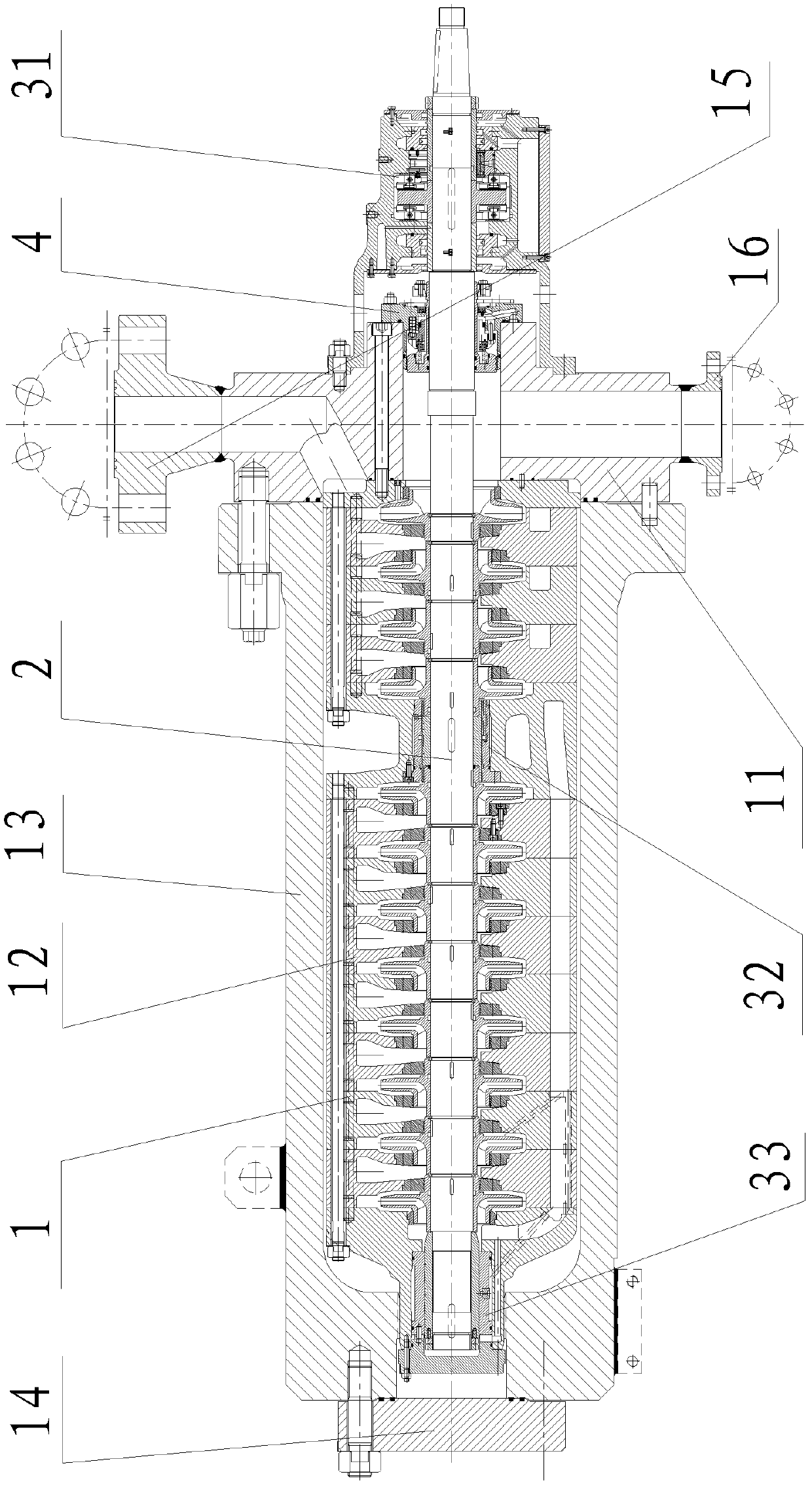
[0061] see figure 1 , the present invention please refer to figure 1 , The upper charging pump used in nuclear power plants includes a stator part 1, a rotor part 2, a bearing part and a shaft sealing device 4. The bearing components include a driving end bearing 31 , an intermediate auxiliary bearing 32 and a non-driving end bearing 33 .

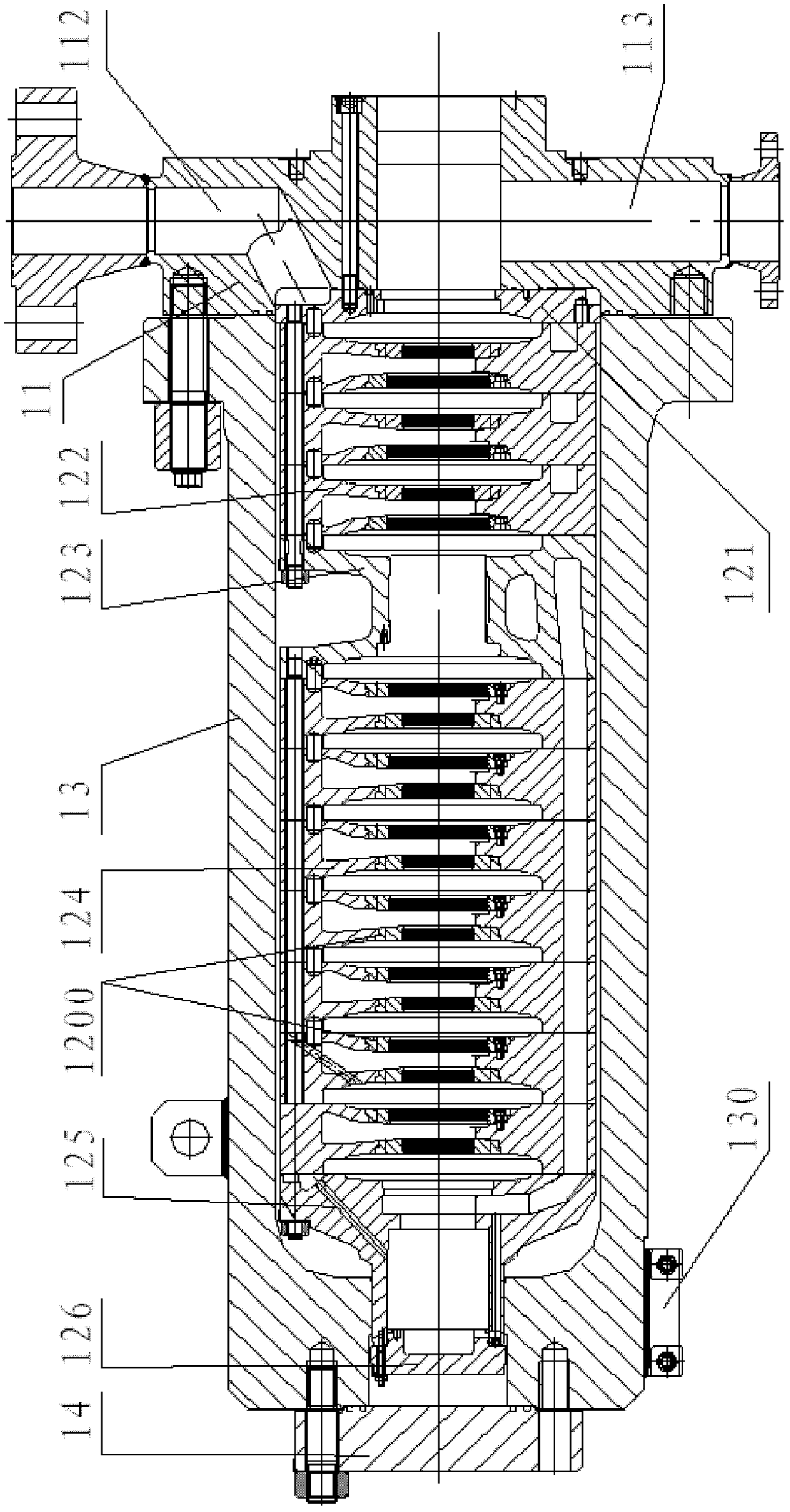
[0062] see again figure 2 , The stator part of the upper charging pump used in the nuclear power plant of the present invention includes a pump head 11, a cylinder body and a tail plate 14 which are sequentially connected back and forth. Among them, the barrel includes an outer shell 12 and an inner shell 13, and a barrel slideway block 130 is provided at the connecting position between the barrel and the pump base to ensure high repositio...


PUM


Abstract

The invention discloses a charging pump for a nuclear power station, which comprises a stator component, a rotor component, a bearing component and a shaft sealing device. The stator component comprises a pump head, a barrel and a tail board, the barrel comprises an outer shell and an inner shell, the rotor component comprises a rotary shaft, an impeller, a middle shaft sleeve, a front shaft sleeve, a thrust disc, a positioning sleeve and a rear bearing sleeve, wherein the impeller, the middle shaft sleeve, the front shaft sleeve, the thrust disc, the positioning sleeve and the rear bearing sleeve are sleeved on the rotary shaft, and the bearing component comprises a drive-end bearing, a middle auxiliary bearing and a non-driven-end bearing. The charging pump for the nuclear power station has the advantages that the size of the charging pump can be reduced, special performance requirements of the charging pump are met, and working efficiency is high.

Description

technical field [0001] The invention relates to an upper charge pump for a nuclear power plant, in particular to an upper charge pump for a nuclear power plant. Background technique [0002] The top charge pump is an important part of the chemical and volume control system (RCV), the main functions of the top charge pump are as follows: [0003] 1) Provide upfill water flow to the reactor coolant system to maintain the normal liquid level in the pressurizer; [0004] 2) Provide cooling water to the No. 1 seal of the three reactor coolant pumps, and this water flow also plays a role in preventing high-temperature coolant from leaking through the seal; [0005] 3) Used as a safety injection pump to prevent core exposure in loss of water events (LOCA). [0006] The charging pumps currently used in nuclear power plants are usually horizontal, double-casing, multi-stage centrifugal pumps. When the centrifugal pump runs at high speed, it will generate a large axial force. In ad...

Claims


Application Information

Patent Timeline
Patent Type & Authority Applications(China)
IPC IPC(8): F04D1/06F04D29/42F04D29/10F04D29/046F04D29/70
CPCF04D1/066F04D29/126F04D29/0473F04D29/42F04D29/0413F04D29/4293F04D7/08F04D29/426F04D29/041F04D29/70F04D29/046F04D29/10F04D1/06
Inventor 陆金琪毛燕萍
Owner SHANGHAI APOLLO MACHINERY
Why Eureka
Try Eureka