
Bolt error-proofing device of machine tool

A technology of bolts and machine tools, applied in positioning devices, metal processing machinery parts, clamping, etc., can solve problems such as tool damage, power head precision damage, and workpiece scrapping, so as to prevent tool collisions and improve safety and reliability. Effect

Inactive Publication Date: 2014-08-27
GUANGXI YUCHAI MASCH CO LTD
View PDF6 Cites 3 Cited by
  • Summary
  • Abstract
  • Description
  • Claims
  • Application Information

AI Technical Summary

Problems solved by technology

When the bolt action is performed on this basically closed machine tool, it can only detect whether the positioning pin protrudes in place (the bolt is in place), but cannot detect the situation that the workpiece is jacked up due to the incorrect bolt. Due to the limitation and the influence of cutting fluid corrosion, it is inconvenient to install a detection switch in the clamp body to detect the position of the workpiece that is jacked up due to incorrect latch. If the workpiece is jacked up, the operator cannot find it in time.
[0004] In addition, due to the precise cooperation between the positioning hole of the workpiece and the positioning pin of the machine tool, the detection of the feeding position is carried out by detecting the conveying rod instead of the workpiece. If the hole itself deviates, the pin will not be correct and the workpiece will be lifted up. At this time, the signal of the pin in place is still connected. At this time, the workpiece will collide with the tool, causing the workpiece to be scrapped, the tool to be damaged, and the precision of the power head to be damaged. Serious accidents

Method used


Image

  • Bolt error-proofing device of machine tool
  • Bolt error-proofing device of machine tool
  • Bolt error-proofing device of machine tool

Examples


Embodiment Construction

[0023] The specific embodiments of the present invention will be described in detail below with reference to the accompanying drawings, but it should be understood that the protection scope of the present invention is not limited by the specific embodiments.

[0024] Unless otherwise expressly stated otherwise, throughout the specification and claims, the term "comprising" or its transformations such as "including" or "including" will be understood to include the stated elements or components, and not Other elements or other components are not excluded.

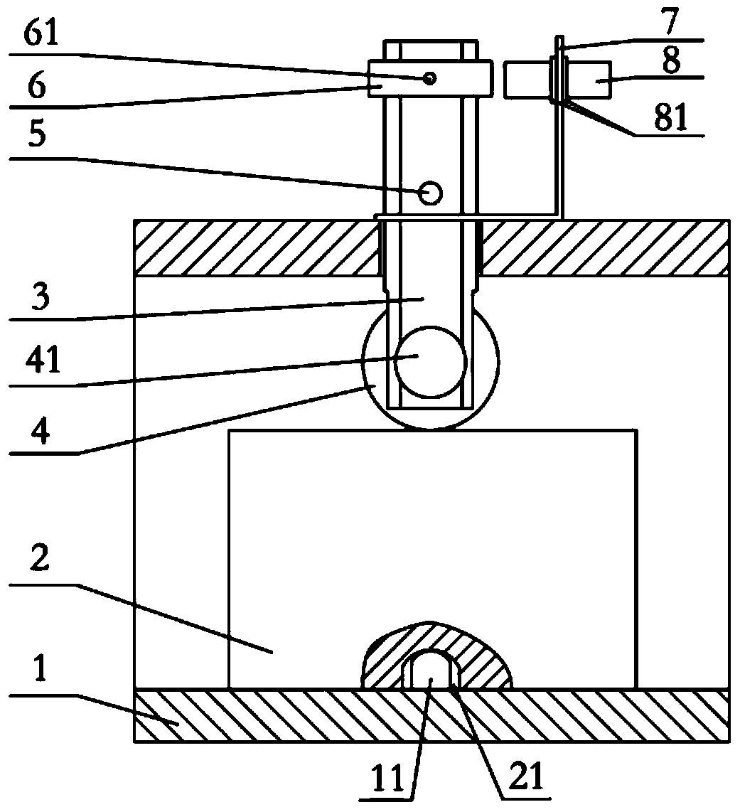
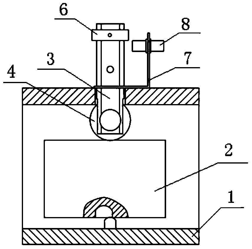
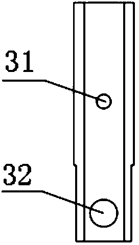
[0025] Such as figure 1 As shown in the figure, according to a specific embodiment of the present invention, a latch error prevention device for a machine tool is installed on the top surface of the clamp body of the machine tool. The latch error prevention device includes a sliding rod 3, a bearing 4, an induction block 6 and a proximity Switch 8, wherein the sliding rod 3 slidably penetrates the top surface of the clamping body ...


PUM


Abstract

The invention discloses a bolt error-proofing device of a machine tool. The bolt error-proofing device is arranged on the top surface of a clamp body of the machine tool; the bolt error-proofing device comprises a sliding rod, a bearing, an induction block and a proximity switch; the sliding rod is arranged on the top surface of the clamp body in a sliding and penetrating mode; the lower end of the sliding rod extends to an area which is formed in the clamp body and used for placing a workpiece; the bearing is arranged on the lower end portion of the sliding rod; the bearing can be in abutting connection with the upper surface of the workpiece and can roll along the upper surface of the workpiece; the induction block is arranged on the upper end portion of the sliding rod; the proximity switch is fixedly arranged above the top surface of the clamp body; when a bolt of the workpiece is positioned correctly, the induction block is located in an induction area of the proximity switch so as to enable the proximity switch to switch on; when the bolt of the workpiece is positioned incorrectly to jack the workpiece, the induction block is far away from the induction area of the proximity switch so as to enable the proximity switch to switch off. According to the bolt error-proofing device of the machine tool, the safety and the reliability of equipment operation can be improved and the damage cost of a cutting tool and the workpiece is reduced.

Description

Technical field [0001] The invention relates to the field of machine tool processing, in particular to a bolt error prevention device of a machine tool. Background technique [0002] At present, combined machine tools or combined machine tool automatic lines are widely used to drill, tap, expand, ream, and boring workpieces. In workpiece processing, it is necessary to locate the workpiece on the machine tool clamp, and workpiece positioning bolts are commonly used Bottom latch. Workpiece processing adopts PLC (Programmable Logic Controller) electrical control, and the machine tool action sequence is generally: feeding-feeding in place-latch-latch in place-clamping-clamping in place-power head fast forward (work advance)-processing the workpiece. [0003] For the above-mentioned machine tool clamp, except for the through hole for passing the tool and installing the clamping mechanism, its bottom, front and rear ends are all closed, and only the left and right ends are the entrance ...

Claims


Application Information

Patent Timeline
IPC IPC(8): B23Q11/00B23Q3/18
CPCB23Q17/2208
Inventor 刘荣根宁杰
Owner GUANGXI YUCHAI MASCH CO LTD
Learn More