Drum washing machine drainage structure and method

A technology of drum washing machine and drainage structure, which is applied to other washing machines, washing devices, textiles and paper making, etc., which can solve the problems of residual water freezing, peculiar smell, re-use after a long time, troubles, etc., and achieve convenient drainage and emptying Effect

Active Publication Date: 2014-08-27
SUZHOU SAMSUNG ELECTRONICS CO LTD +1
View PDF4 Cites 11 Cited by
  • Summary
  • Abstract
  • Description
  • Claims
  • Application Information

AI Technical Summary

Problems solved by technology

However, because the upper drainage method is limited by the head of the drainage pump, the water cannot be completely discharged, and at least part of the water will remain in the drainage pipe. Odor, this part of the water will mix with the new water when it is used again after a long time, polluting the clothes; in winter, when the washing machine is placed in an environment below the freezing point, there is a risk of residual water freezing, causing the blades to rotate and break the ice the next time it is started The abnormal noise of the block will damage the structure of the impeller of the drainage pump and affect the normal use of the machine.
[0003] Therefore, in view of the situation that the residual water cannot be completely discharged, generally the washing machine adds a drain port at the lowest point of the pump casing, connects a manual drain pipe, and performs manual drainage. This drainage structure can ensure that the residual water is completely discharged, but the disadvantage is that it requires the user to Manual operation, the user must temporarily find the water storage volume to receive the water, and the user must find a storage container to receive the water when using it, otherwise, after removing the pipe plug, the residual water will be directly discharged on the ground without receiving the residual water, which will be caused by the residual water. The amount of residual water is large, so that a large amount of water will flow on the ground, causing additional trouble

Method used


Image

  • Drum washing machine drainage structure and method
  • Drum washing machine drainage structure and method

Examples


Embodiment Construction

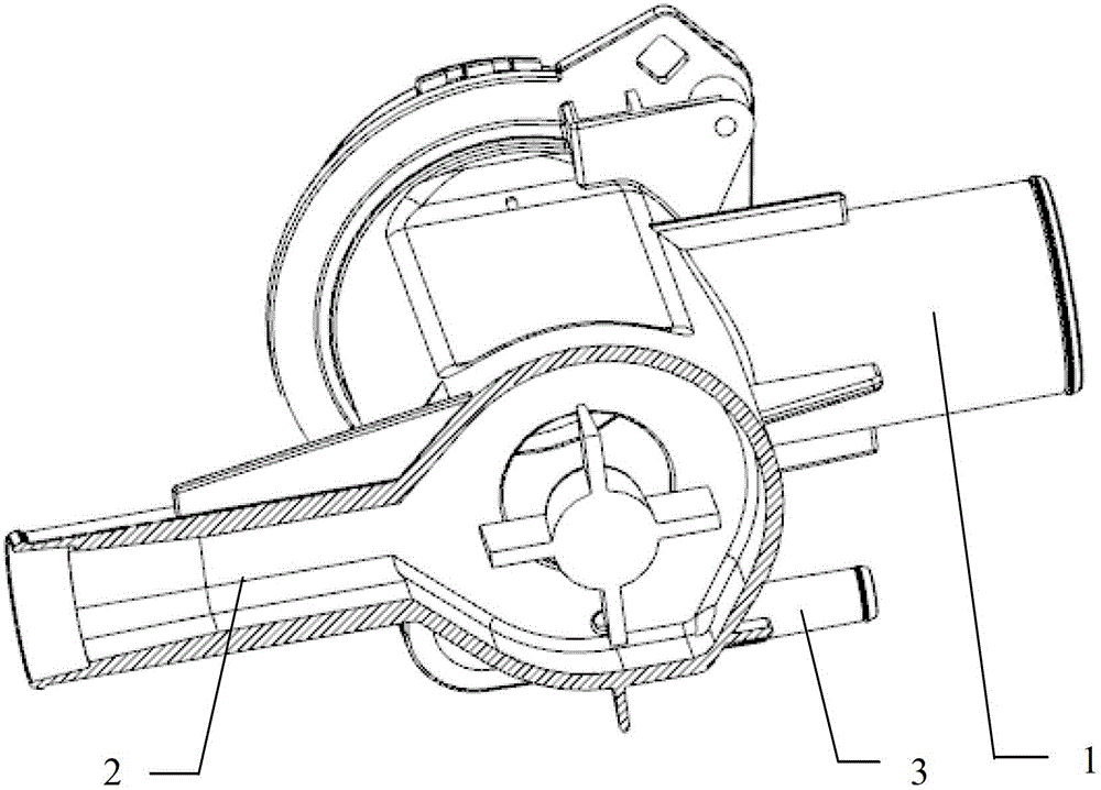
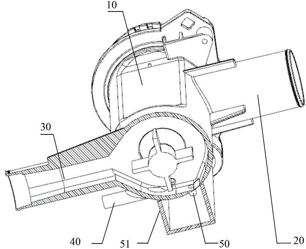
[0029] The invention discloses a drainage structure of a drum washing machine, which includes a drainage pump. The drainage pump includes a pump casing and an impeller located in the pump casing. The pump casing is provided with a water inlet pipe. The drainage structure also includes:

[0030] a first drain for the first discharge of washing water;

[0031] a second drain for discharging residual wash water after draining through the first drain;

[0032] a third drain for washing water remaining after draining through the first drain or the first drain and the second drain;

[0033] Wherein, the first drain port and the second drain port communicate with the outside of the drain pump through the first drain hose and the second drain hose respectively, forming a first drain passage and a second drain passage respectively;

[0034] The third drain port is directly connected to the outside of the drain pump or connected to the outside of the drain pump through a third drain ho...


PUM


Abstract

The invention discloses a drum washing machine drainage structure and method. The drum washing machine drainage structure comprises a drainage pump; the drainage pump comprises a pump casing and impellers which are arranged inside the pump casing; a water inlet pipe is arranged on the pump casing. The drum washing machine drainage structure is characterized by also comprising a first drainage outlet, a second drainage outlet and a third drainage outlet which are communicated with the interior of the drainage pump; the first drainage outlet is used for draining washing water for the first time; the second drainage outlet is used for draining residual washing water after drainage through the first drainage outlet; the third drainage outlet is used for draining residual washing water after drainage through the first drainage outlet or the first drainage outlet and the second drainage outlet. According to the drum washing machine drainage structure and method, drainage is performed in a drainage pump mode through a first drainage channel and a second drainage channel, residual water is drained manually through a third drainage channel, residual water is effectively reduced due to the secondary up drain, and accordingly a user can conveniently drain or empty the residual water.

Description

technical field [0001] The invention relates to the technical field of drum washing machine drainage, in particular to a drum washing machine drainage structure and method. Background technique [0002] The residual water removal structure of the existing upper drainage type drum washing machine is as follows: figure 1 The main components shown include a drainage pump and a casing, a water inlet pipe 1 , a main drainage pipe connection 2 , and a manual drainage pipe connection 3 . When draining water, the water discharged from the outer cylinder of the washing machine flows into the area of ​​the rotating impeller along the axial direction of the drainage pump through the water inlet pipe 1, and flows out along the radial direction of the blades along the main drainage pipe after being acted by the impeller. However, because the upper drainage method is limited by the head of the drainage pump, the water cannot be completely discharged, and at least part of the water will r...

Claims


Application Information

Patent Timeline
Patent Type & Authority Applications(China)
IPC IPC(8): D06F39/08
CPCD06F39/085
Inventor 谭永学
Owner SUZHOU SAMSUNG ELECTRONICS CO LTD
Why Eureka
Try Eureka