Axial flow wind wheel and air conditioner with same
A technology of axial flow wind and wind wheel, which is applied to components of pumping devices for elastic fluids, non-variable pumps, machines/engines, etc., and can solve the problems affecting room temperature rise, temperature drop speed, air disturbance, Issues such as short air supply distance to improve the air outlet effect and improve the overall performance
- Summary
- Abstract
- Description
- Claims
- Application Information
AI Technical Summary
Problems solved by technology
Method used
Image
Examples
Embodiment 1
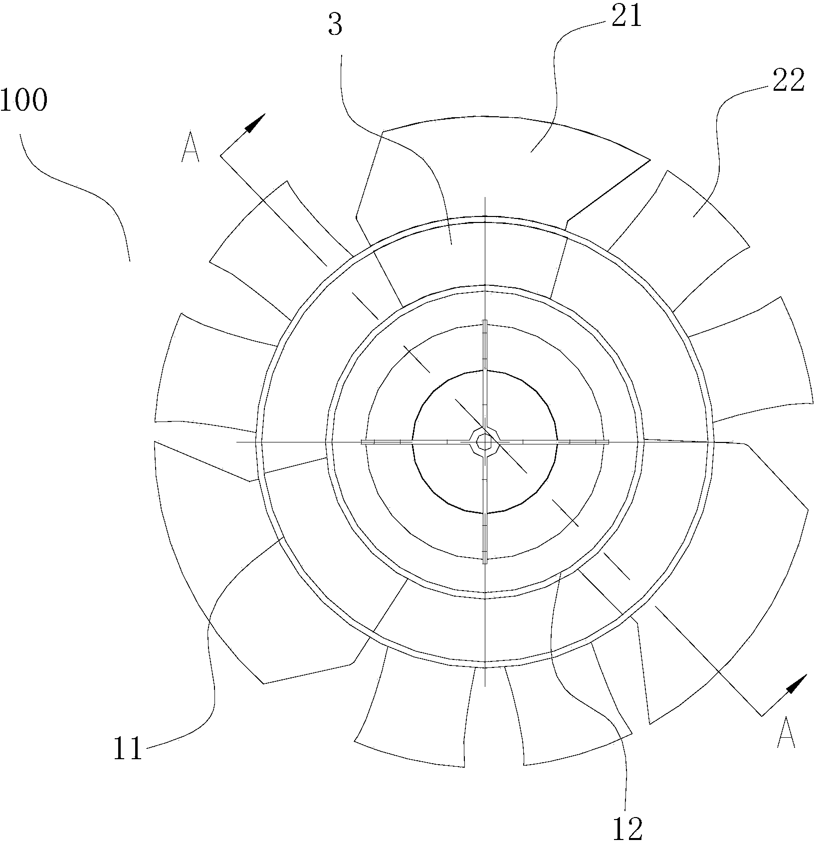
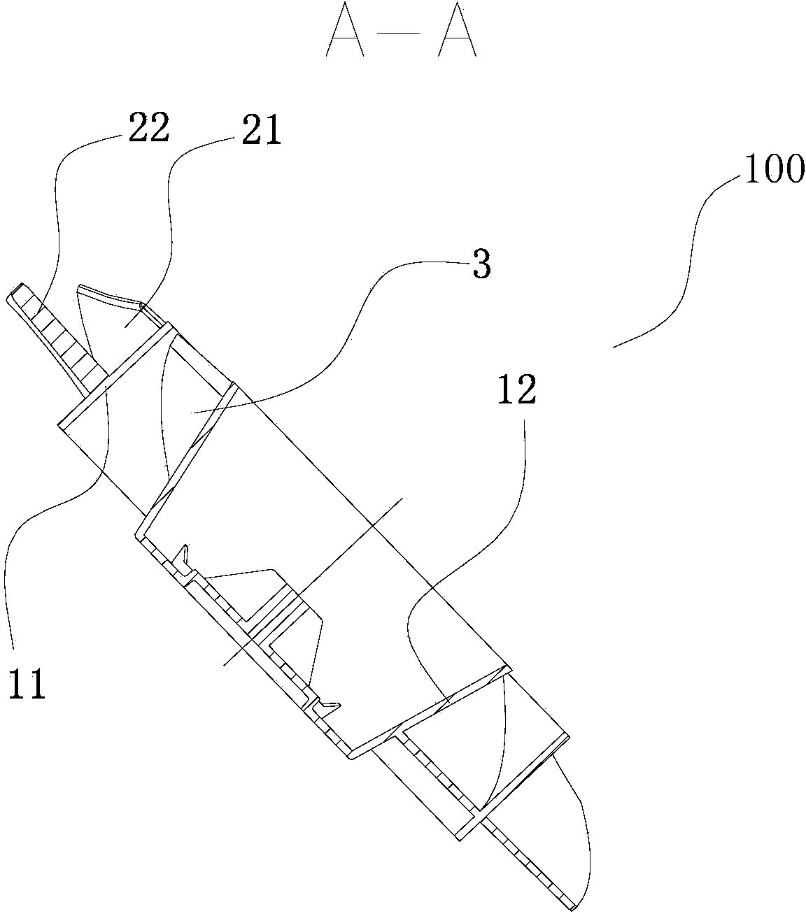
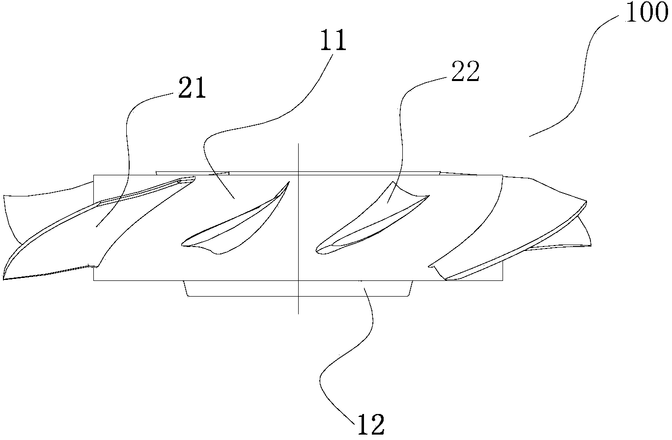
[0098] refer to Figure 1-Figure 3 , the axial flow wind wheel 100 comprises: a coaxial inner hub 12 and an outer hub 11, three evenly distributed inner blades 3 are arranged between the inner hub 12 and the outer hub 11, and three evenly distributed first blades 3 are arranged on the outer hub 11. Outer blades 21 and six evenly distributed second outer blades 22, wherein the three inner blades 3 correspond to the three first outer blades 21 in the circumferential direction of the outer hub 11, and each corresponding inner blade 3 corresponds to Each first outer blade 21 can constitute a small hub ratio propeller axial flow blade 2000 with a complete aerodynamic configuration, and two second outer blades 22 are arranged between each adjacent two first outer blades 21, each The second outer blades 22 are axial flow blades 3000 with a large hub ratio, and the rotation planes of the inner blades 3 and the outer blades are approximately in the same plane, thereby reducing the desi...
Embodiment 2
[0102] like Figure 4 As shown, the structure of this embodiment is substantially the same as that of Embodiment 1, wherein the same components use the same reference numerals, and the only difference is that the three inner blades 3 and the three first outer blades 21 are located on the circumference of the outer hub 11. Up is not a one-to-one correspondence, but staggered from each other.
[0103] refer to Figure 4 , the connection line between the installation position of each first outer blade 21 on the inner peripheral wall of the outer hub 11 and the center of the outer hub 11, and the closest inner blade 3 (that is, the closest inner blade to the outer hub 11 in the circumferential direction) 3) There is a certain angle α between the installation position on the inner peripheral wall of the outer hub 11 and the line connecting the center of the outer hub 11, so that the periodic pressure pulsation noise ( That is, the waveforms of the rotation noise of the axial flow...
Embodiment 3
[0105] like Figure 5 As shown, the structure of the present embodiment is substantially the same as that of the second embodiment, wherein the same components use the same reference numerals, and the only difference is that the number of inner blades 3 is different.
[0106] refer to Figure 5 , there are five evenly distributed inner blades 3 between the inner hub 12 and the outer hub 11, so that by adjusting the number of inner blades 3, the overall air supply volume of the axial flow rotor 100 can be improved and the axial flow rotor 100 can be reduced. power and noise.
PUM
 Abstract
Description
Claims
Application Information
 - R&D
- Intellectual Property
- Life Sciences
- Materials
- Tech Scout
- Unparalleled Data Quality
- Higher Quality Content
- 60% Fewer Hallucinations
Browse by: Latest US Patents, China's latest patents, Technical Efficacy Thesaurus, Application Domain, Technology Topic, Popular Technical Reports.
© 2025 PatSnap. All rights reserved.Legal|Privacy policy|Modern Slavery Act Transparency Statement|Sitemap|About US| Contact US: help@patsnap.com


