Eureka AIR delivers breakthrough ideas for toughest innovation challenges, trusted by R&D personnel around the world.

Sliding rotating shaft mechanism and armrest box armrest

A technology of hinge and armrest cover, which is applied in the direction of pivot connection, passenger space, etc., to achieve the effect of reducing restrictions and meeting different requirements of comfort

Inactive Publication Date: 2014-08-27
SHANGHAIK YANFENG JINQIAO AUTOMOTIVE TRIM SYSTEMS CO LTD
View PDF6 Cites 2 Cited by
  • Summary
  • Abstract
  • Description
  • Claims
  • Application Information

AI Technical Summary

Problems solved by technology

[0004] However, because the rotation of the above-mentioned existing handrails is realized only by one fixed rotation axis, that is, the trajectories of the handrails are all circular trajectories, and the single rotation axis is relatively limited by the space, and the part structure can only be arranged in a small range , therefore, there will be specific restrictions on the shape of the surrounding parts or the space required by the mechanism

Method used


Image

  • Sliding rotating shaft mechanism and armrest box armrest
  • Sliding rotating shaft mechanism and armrest box armrest
  • Sliding rotating shaft mechanism and armrest box armrest

Examples


Embodiment Construction

[0070] Below in conjunction with the drawings, preferred embodiments of the present invention are given and described in detail.

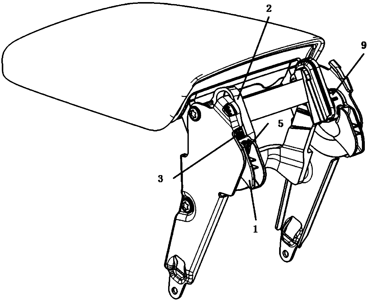
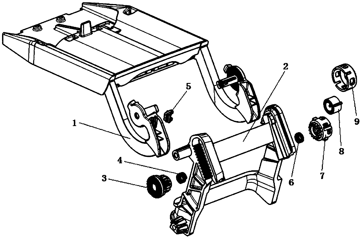
[0071] see Figure 1-25 , In the following embodiments, the armrest of the armrest box with the sliding and rotating shaft mechanism of the present invention is taken as an example. The present invention is a sliding and rotating shaft mechanism, which includes: a sliding and rotating cantilever 1, a sliding and rotating track bracket 2, a straight-toothed one-way ratchet 3, a left helical spring 4, a stop spring 5, a right helical spring 6, and a straight tooth Coil spring guard 7, coil spring 8 and two-way ratchet guard 9.

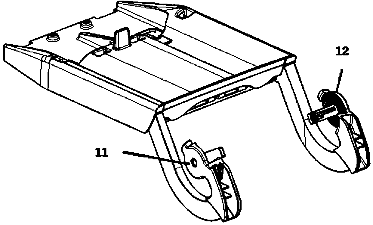
[0072] The sliding and rotating cantilever 1 is generally integrated on the armrest cover part, which includes a left arm 11 and a right arm 12 arranged at intervals on the left and right, wherein:

[0073] One end of left arm 11 is connected on the armrest cover plate part, and its other end has: left installation wall 110...


PUM


Abstract

The invention relates to a sliding rotating shaft mechanism and an armrest box armrest. The sliding rotating shaft mechanism comprises a sliding rotating cantilever, a sliding rotating rail support, a straight tooth one-way ratchet wheel, a left spiral spring, a check spring piece, a right spiral spring, a straight tooth coil spring protective cover, a coil spring and a two-way ratchet wheel protective cover, wherein one end of the sliding rotating cantilever is integrated onto an armrest cover plate part, the sliding rotating cantilever comprises a left arm and a right arm, the left arm and the right arm are arranged in a left-and-right spaced mode, the sliding rotating rail support comprises a left sliding rotating rail and a right sliding rotating rail, and the left sliding rotating rail and the right sliding rotating rail are arranged in a left-and-right spaced mode. Linear rails and rotary rails are adopted, the armrest slides linearly and then move rotatably through matching of the ratchet wheel, gears, toothed rails, springs and the like, and therefore limits of the mechanism on armrest modeling and spatial arrangement are reduced; the armrest achieves the functions of damping and stagnation close to any position, and can achieve the function of automatic returning of the mechanism.

Description

technical field [0001] The invention relates to a turning device for an armrest of an auxiliary instrument panel of an automobile, in particular to a sliding and rotating shaft mechanism and an armrest of an armrest box. Background technique [0002] According to the requirements of different configurations, the sub-dashboard of the car will be equipped with armrest assembly parts to provide a comfortable elbow position for the driver or passenger. At the same time, most armrest assemblies have the function of flipping and opening. To design a storage space, the armrest is equivalent to a storage box cover. However, under normal circumstances, as far as the armrest function is concerned, most armrests can only provide the support function of the occupant's elbow when they are closed, and they cannot support the force after they are opened. Therefore, such an armrest assembly has a single position and cannot Meet the body size or needs of as many occupants as possible. [0...

Claims


Application Information

Patent Timeline
IPC IPC(8): F16C11/10B60R7/06
Inventor 张俊玮卜海涛丁小芹
Owner SHANGHAIK YANFENG JINQIAO AUTOMOTIVE TRIM SYSTEMS CO LTD
Why Eureka
Eureka Blog
Learn More