
Converter valve tower and valve hall with converter valve tower

A technology for diverter valves and valve towers, applied in the field of diverter valve towers, which can solve problems such as inconvenient maintenance of diverter valve towers, and achieve the effects of improving installation and maintenance efficiency, increasing installation and maintenance space, and reducing size

Active Publication Date: 2014-08-27
XJ ELECTRIC
View PDF8 Cites 22 Cited by
  • Summary
  • Abstract
  • Description
  • Claims
  • Application Information

AI Technical Summary

Problems solved by technology

[0003] The purpose of the present invention is to provide a diverter valve tower to solve the problem of inconvenient maintenance of the existing diverter valve tower

Method used


Image

  • Converter valve tower and valve hall with converter valve tower
  • Converter valve tower and valve hall with converter valve tower

Examples


Embodiment Construction

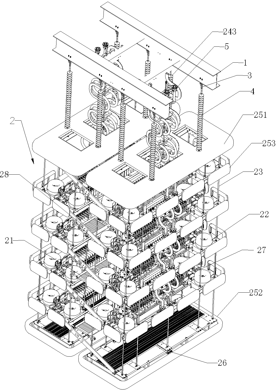
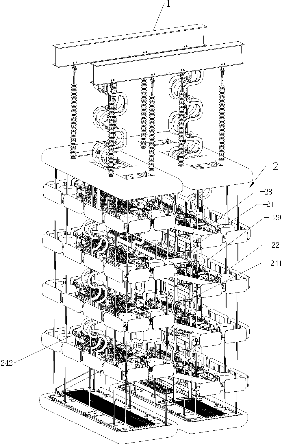
[0021] Embodiment 1 of the valve hall of the present invention, such as Figure 1-2 As shown: the valve hall includes a steel beam 1 and a converter valve tower 2, and the converter valve tower 2 is suspended under the steel beam 1.

[0022] The diverter valve tower 2 includes two rows of diverter valve assemblies arranged at intervals on the left and right, and an inspection platform 21 is provided between the two rows of diverter valve assemblies, and there are two diverter valve assemblies 22 in each row of diverter valve assemblies. The above and from top to bottom are arranged in layers, and two rows of converter valve assemblies are arranged in staggered layers, wherein any converter valve assembly on one row of converter valve assemblies is in the same position as any converter valve assembly on the other row of converter valve assemblies. different heights.

[0023] In order to facilitate the adjustment of the installation distance between adjacent converter valve ass...


PUM


Abstract

The invention relates to a converter valve tower and a valve hall with the converter valve tower. The converter valve tower comprises two rows of converter tower assemblies arranged in a spaced mode. An overhaul platform is arranged between the two rows of converter tower assemblies. Each row of converter valve assemblies includes two or more converter valve assemblies which are arranged in a layered mode from top to bottom. The two rows of converter valve assemblies are arranged in different layers. Due to the fact that the two rows of converter valve assemblies are arranged in different layers, the installation and maintenance space for each converter valve assembly can be enlarged; in the on-site installation and overhaul process, working staff stand on the overhaul platform and can freely change the working postures and select comfortable work stations, and therefore any converter valve assembly can be conveniently and freely overhauled, installation and maintenance efficiency is greatly improved, and the problem that an existing converter valve tower is not convenient to overhaul is solved.

Description

technical field [0001] The invention relates to a diverter valve tower and a valve hall using the diverter valve tower. Background technique [0002] The valve hall includes a steel beam and a converter valve tower suspended under the steel beam. The thyristor converter valve tower disclosed in the Chinese patent document with application number 201310255576.8 is a common converter valve tower. The converter valve tower includes two rows of converter valve assemblies, and each row of converter valve assemblies includes two The above valve layers are stacked from top to bottom, and the same valve layer of each row of converter valve assemblies is arranged side by side at intervals and fixed together. There is a maintenance channel for maintenance personnel to enter and exit between the two rows of converter valve assemblies. Layers of converter valve assemblies are connected in series. At least one layer of maintenance platform is arranged in the maintenance channel, and th...

Claims


Application Information

Patent Timeline
IPC IPC(8): H02M7/00
CPCH02M7/00
Inventor 朱新华张建肖晋李申王艳李华君谢云龙姚志国
Owner XJ ELECTRIC
Learn More